Advertisement
Quick Links
Advertisement

Related Manuals for Signode TENSION-WELD VT-32


Summary of Contents for Signode TENSION-WELD VT-32
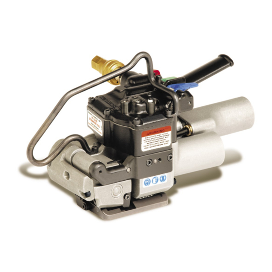
- Page 1 VT-32 TENSION-WELD® STRAPPING TOOL...
- Page 2 Use the correct Signode products for your application. 2. TRAINING. This tool must not be used by persons not properly trained in its use. Be certain that you receive proper training from your employer. If you have any questions contact your Signode Representative. 3. EYE INJURY HAZARD.
- Page 3 7. WORK AREA. Keep work areas uncluttered and well lighted. Several types of strap can be used with this tool. Use the correct Signode products for your application. If you need help contact your Signode Representative. SAFETY PROCEDURES FOR TOOL OPERATION Before using this tool, read its Operation and Safety instructions.
- Page 4 General Safety Instructions Parts List, Air Motors Specifications Troubleshooting Major Components Maintenance Pneumatic Information Tool Options Operating Instructions Adjustments VT-32 Strapping Tool, Signode Part No. 428150 SPECIFICATIONS STRAP MODEL TYPE WIDTH THICKNESS HIGH STRENGTH 0.040" to 0.050" VT-25 HD 32mm TENAX (1.0mm - 1.3mm)
- Page 5 MAJOR COMPONENTS...
- Page 6 Filter-Regulator-Lubricator Unit, 1/2" NPT (Signode Part No. 424773) FRL Mounting Bracket (Signode Part No. 071982) Air Hose, 1/2" ID, 3/8" Fittings (Signode Part No.
- Page 7 The remaining moisture is removed at the water leg in the piping system or in the filter (Part No. 008559). NOTE: Additional information is available in the Signode publication, "Air Supply Manual" (Part No. 186038). If you have any questions, contact your local Signode Representative.
- Page 8 Air pressure is assumed to be 90 psig (6.2 Bar) with recommended size and length of air hose. Volume of air is at room temperature and sea level pressure, or so-called "free air" conditions. For more detailed information about air supply systems refer to Signode manual Part No. 186038.
- Page 9 An air line dryer adjacent to the compressor. b. Use lubricant recommended by Signode. Signode has tested the use of anti-freezes, none work well in air tool; the tool will gum up when anti-freezes are introduced and will not function properly.
- Page 10 PNEUMATIC INFORMATION, Continued AIR PRESSURE INDICATOR The VT-32 is equipped with an air pressure indicator built into the tool. During the sealing step of the tool operation a Blue pressure indicator will pop up from the tool cover (as shown) indicating that there is at least 70psi of supply air pressure.
- Page 11 OPERATING INSTRUCTIONS Wear safety glasses. Stand to one side of the strap when tensioning. Make sure all bystanders are clear before proceeding. PLEASE NOTE: Do not operate tool without strap, as damage to the tool may occur. 1. With the dispenser placed behind you, bring the strap over the top and around the package, place the straps together and...
- Page 12 3. Recheck the strap alignment at the rear of the tool and realign if necessary. Release the tension motor. Press down the Green Tension Control Lever to begin tensioning the strap. When the tension motor stalls, indicating completion of tension, release the control lever. The strap will remain tensioned around the package.
- Page 13 OPERATING INSTRUCTIONS, Continued 5. The internal weld timer is energized. The main piston brings the welding pads together and the strap is welded. The supply end of the strap is then cut off. Pull the cut strap away from the tool during welding.
- Page 14 7. Swing the tool out from the completed strap joint. Inspect the joint to make sure the straps have been properly welded. STRAP JOINT INSPECTION This tool is a Tension Weld® type sealer. A properly made joint will appear as shown in the illustration.
- Page 15 4. If you are unable to produce an acceptable joint or if you have any questions as to whether your tool is producing good weld strength, contact your Signode Sales Representative. LOCATION OF WELD TIME ADJUSTMENT 5. Replace the cap over the screw.
- Page 16 (Key 98) as shown by arrow, in 1/4 increment turns counter-clockwise to increase strap tension and clockwise to reduce strap tension. Use the 4mm hexwrench (Signode Part No. 274467) included with every new tool. NOTE: Operating air pressure must be set between 85 and 90 psi (5.7-6.2 Bar).
- Page 17 TOOL ADJUSTMENTS, Continued STRAP CUTTER The VT strap cutter has two serrated cutting edges. After the first edge has become dull or strap cut-off becomes difficult the blade can be remounted to use the second cutting edge. Once both edges have become worn the blade should be replaced.
- Page 18 PARTS LIST PART NO DESCRIPTION 425648 OIL SEAL 008734 BEARING FAFNIR B-542 010035 SHCS M6 X 18 LG 011214 SHCS M5 X 16 LG 426146 ROLLER BEARING 020704 HANSEN PLUG L-15 015293 SOCKET L-15 020728 O-RING SAE # 007 022789 O-RING SAE # 016 425645 O-RING SAE # 123...
- Page 19 424552 Only use valve cartridge (Key 106), 423953 WARNING LABEL 428154 OUTER GUIDE(32) Signode Part No. 424550. Cartridges can 428153 CUTTER INSERT (32) be identified by the OEM code “D2073" 424495 CUTTER GUIDE marked on the back surface of the part.
- Page 20 Install Key 120 (Needle Bearing) flush with rear wall of gear housing as shown in Figure “A” below. Key numbers 124, 125, 126 and 127 can be order together as Signode Part Number 426159. Install Key 125 (Needle Bearing) in to Key 127 (Worm Gear) bottomed out against Key 126 (Spacer) as shown in Figure “B”...
- Page 21 NEVER remove the air valves (Key 79, 100 & 106) when air is connected to the tool. Removing an valve with air to the tool will cause the valve to violently release from the tool.
- Page 22 * Use Loctite #242 or equivalent. ** Use Loctite #609 or equivalent.
- Page 23 PARTS LIST, TENSION MOTOR 426155 PART NO DESCRIPTION 426124 MOTOR HOUSING 424154 BACK END PLATE 422815 CYLINDER 425468 ROTOR 024602 SPACER 425469 FRONT END PLATE 023481 BALL BEARING 426602 BRAKE 426145 ROLLER CLUTCH 426128 RELEASE PIN 426127 ECCENTRIC 423493 Ø5 X 16 DOWEL PIN 426611 LEVER(MACH) 426138...
- Page 25 PARTS LIST, WELD MOTOR 428213 PART NO DESCRIPTION 080315 RETAINING RING 424181 FLAT WASHER 014541 BELLEVILLE WASHER 090118 BALL BEARING 423973 FRONT END PLATE 024602 SPACER 424172 O-RING 424174 ROTOR 422818 VANE 424164 LOCK PIN 422815 CYLINDER 424154 BACK END PLATE 424161 BALL BEARING 428157...
- Page 26 TROUBLESHOOTING The following items are the most common types of tool malfunctions. For symptoms or remedies not shown, contact your Signode service representative for additional information and details. The following tool conditions are shown in this manual: AIR SUPPLY #1 - The air motor is frozen.
- Page 27 CAUSE REMEDY Feedwheel is clogged with dirt or strap residue. Clean teeth on feedwheel with the cleaning brush (Signode Part No. 023963) provided. Worn teeth on the feedwheel. Replace the feedwheel. Excessive or improperly set feedwheel to gripper Adjust feedwheel gap as required.
- Page 28 #7 CONDITION: A poor weld identified by an incomplete area of weld. CAUSE REMEDY Welding is achieved by a combination of vibration and Dismantle and clean the weld mechanism by brushing downward pressure of the upper gripper. Either a away the strap residue or washing the entire unit in a restriction of motion or a reduction of downward solvent.
- Page 29 TROUBLESHOOTING, Continued #11 CONDITION: Strap weld time is erratic. CAUSE REMEDY Air leakage in timing circuit. Check o-rings and pneumatic components for leaks. Replace parts as required. Dirty or very dry pilot valve (Key 106). Remove, clean and lubricate the pilot valve using air line oil or replace if needed.
- Page 30 MAINTENANCE TOOL 1. Clean the teeth on the feedwheel and the gripper plug with the special brush provided. 3. Periodically clean the tool with compressed air. 4. Disassemble, clean and lubricate the welding mechanism. GEAR HOUSING Periodically check the gear housing portion of the tool: 1.
- Page 31 The VT can be suspended in various operating positions by using the proper tool hanger and hardware. Review the illustrations below for the appropriate configuration for the tool application. Applications are recommended to use an Overhead Tool Balancer as shown (Signode Part No. 306809). HORIZONTAL SEALING...
- Page 32 OPTIONAL 3-WAY TOOL HANGER, PART NO. 425235 This option allows the operator to suspend the VT tool from its side to allow for easier horizontal strapping applications as well as top and side sealing applications. The hanger replaces the standard VT tool hanger. NOTE: Hanger is supplied with additional M5x16 socket head cap screws (Part No.
- Page 35 It is hereby declared that the undermentioned machinery has been designed and constructed to comply with the health and safety requirements defined in EC Directive 89/392/EEC Machine Supplier: Signode, Division of ITW Ltd. Queensway, Fforestfach Swansea SA5 4ED Machine Description:...
- Page 36 Glenview, Illinois plant, any tool which proves to not operate per functional specifications within the stated period. Signode reserves the right to replace any tool which proves not to operate per functional specifications with a new or like-new tool of the same model if in Signode's judgement such replacement is appropriate.
Need help?
Do you have a question about the TENSION-WELD VT-32 and is the answer not in the manual?
Questions and answers