Table of Contents
Advertisement
Advertisement
Chapters
Table of Contents

Related Manuals for Signode TABLE-TYER


Summary of Contents for Signode TABLE-TYER
- Page 1 12/14/10...
-
Page 2: Table Of Contents
12/14/10 CONGRATULATIONS Thank you for purchasing your Table-Tyer Strapping Machine. The Table-Tyer has been designed to be a reliable, maintenance free strapping machine. The innovative design of this machine allows for every maintenance part to be replaced easily and quickly with very little or no instruction. -
Page 3: Safety Information
6. Follow all maintenance and service instructions in this manual. MOVING MACHINE PARTS 1. Disconnect and lock out all power to Signode's machines before entering the strap chute area. 2. Never put any part of your body into the strap chute area or machine enclosure with machine power on. - Page 4 4. Before performing service in the strap chute area, disconnect and lockout machine power. MOVING THE MACHINE Wheel kits are standard for Signode general purpose machines. A forklift may be used to transport the machine from one location to another. Consult your employer for proper lifting and handling...
-
Page 5: Specifications
12/14/10 TABLE-TYER, MACHINE SPECIFICATIONS STRAP SIZES: Signode Empax 1/4" (6mm), 3/8" (9mm), 1/2" (12mm) PACKAGE SIZE (Minimum): 3 1/2" W x 1-1/2" H VOLTAGE SPECIFICATIONS: Rated current: Rated voltage: 110V Rated frequency: 6OHz Type of current: FAULT PROTECTION: Fused SYSTEM DISCONNECT:... -
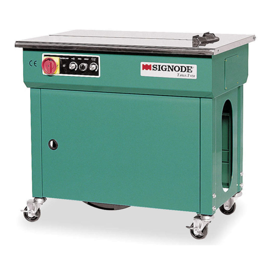
Page 6: Major Components
2. Heater lamp, lamp will light on when proper sealing temperature is reached 3. Potentiometer, strap feed length 4. Button, strap feed and reset 5. Potentiometer, strap tension adjustment 6. Table top, hinge 7. Strap reel 8. Caster (2 locking) 9. Adjustable legs (Table-Tyer) 10. Frame 11. Access Door... - Page 7 12/14/10...
-
Page 8: Disconnect & Lockout
12/14/10 MACHINE DISCONNECT AND LOCK-OUT PROCEDURES This machine is equipped with shut off devices which satisfy OSHA Regulation 1910.147 (control of hazardous energy sources - lock out/tag out). Become familiar with the location, and operation of each shutoff device. Disconnect/Lock-Out all power sources before servicing machine. Never use machine operating controls as a means for locking out power. -
Page 9: Electrical Schematic
12/14/10 ELECTRICAL SCHEMATIC, TABLE TYER... - Page 13 12/14/10 MACHINE OPERATION START-UP AND OPERATING SEQUENCE 1. Put strap on the strap reel and thread the strap. 2. Turn main switch QS1 to ON. The heating element reaches the working temperature in approximately 1 minute. 3. Use potentiometer R3 to adjust the strap length. 4.
- Page 14 12/14/10 STRAP TENSION If R4 (strap tension adjustment) is on MAX position make sure that A is turned clockwise until the strap is not sliding between rollers B and C. Reverse action to achieve lower strap tension. MAINTENANCE AND LUBRICATION To ensure that the semi-automatic strapping machine is always ready for proper and reliable operation keep to regular and attentive maintenance.
-
Page 15: Parts List & Views
12/14/10 PARTS LISTS & EXPLODED VIEW INTERNAL GROUPS: Page Control Head Heater Rear Bar Press Bar Front Bar Feed Main Roller Feed Shooter Roller Arm Strap Guide Transmission EXTERNAL: Frame Base Top Plate Reel Unit Reel Control ELECTRICAL: Control Unit Control Components OPTIONS: Indicator Unit... -
Page 16: Control Head
12/14/10 CONTROL HEAD GROUP ASSEMBLY PART NO. DESCRIPTION 500475 Main Body Block 500476 Switch Lever 500477 Switch Pin 500478 Strap Guide (A) 500479 Strap Guide (B) 500480 Switch Bracket 500481 Cutter Holder 500482 Bar Guide Lid 500483 Spring Hook 500484 Shaft 500485 500486... - Page 17 12/14/10...
-
Page 18: Cam
12/14/10... -
Page 19: Heater
12/14/10... -
Page 20: Rear Bar
12/14/10 REAR BAR ASSEMBLY PART NO. DESCRIPTION 500575 Spring Pin, 3x18 500576 Return Spring 500577 Spring Hook 500578 Rear Bar 430129 Plunger 500579 Bearing, 635ZZ 500580 Spring Pin, 5x14 500581 Spring... -
Page 21: Press Bar
12/14/10 PRESS BAR ASSEMBLY PART NO. DESCRIPTION 500584 Press Bar 500575 Spring Pin, 3x18 500576 Return Spring 500577 Spring Hook 430129 Plunger 500579 Bearing, 635ZZ 500580 Spring Pin, 5x14 500581 Spring... -
Page 22: Front Bar
12/14/10 FRONT BAR ASSEMBLY PART NO. DESCRIPTION 500575 Spring Pin, 3x18 500576 Return Spring 500577 Spring Hook 430129 Plunger 500579 Bearing, 635ZZ 500580 Spring Pin, 5x14 500581 Spring 500587 Front Bar... -
Page 23: Feed
12/14/10... -
Page 24: Main Roller
12/14/10 MAIN ROLLER ASSEMBLY PART NO. DESCRIPTION 500599 Main Roller Shaft 500600 Main Roller 500601 Side Plate 500602 Bearing, 6004ZZ 500603 Stop Ring, S-20 500604 Gear 500605 Washer 500508 SW, M6 500495 HBS, M6x16 500496 HBS, M5x12 500606 Key 5x5x35... -
Page 25: Feed Shooter
12/14/10 FEED SHOOTER ASSEMBLY PART NO. DESCRIPTION 500628 Feed Shooter 500500 SW,M5 500512 HBS, M5x16 500629 Ring, S10 500630 Shaft 500631 Roller 500632 PW,M6 500508 SW,M6 500495 HBS, M6x16 500633 HN,M6... -
Page 26: Roller Arm
12/14/10 ROLLER ARM ASSEMBLY PART NO. DESCRIPTION 500607 Tension Arm 500508 Shaft 500609 Connect Rod 500610 Roller Arm 500611 Shaft 500612 Spring 500613 Roller Shaft 500614 Roller 430705 Feed Spring 500616 Washer 500617 500619 HBS, M6x75 500620 HN, M6 500495 HBS, M6x16 500508 SW, M6... - Page 27 12/14/10...
-
Page 28: Strap Guide
12/14/10 430720 Stop 430721 Insert Screw 430722 430723... -
Page 29: Transmission
12/14/10... - Page 30 12/14/10...
-
Page 31: Base
12/14/10 BASE ASSEMBLY PART NO. DESCRIPTION 500652 Frame 500652 Frame 500656 Support 500657 Side cover 500658 Hinge 500659 Grommet 500660 Front Door 500662 Grommet 500663 Fix Plate 430706 Adjustable Leg 500665 Caster (Free) 500666 Caster (Brake) 500667 Magnet Catch 500508 SW, M6 500649 PW, M6... - Page 32 12/14/10...
-
Page 33: Top Plate
12/14/10 TOP PLATE ASSEMBLY PART NO. DESCRIPTION 500686 Package Guide 500687 Shaft 500685 Top Plate 500688 HBS M6x12 500508 SW,M6 500649 PW,M6 500689 WN, M6 500690 TMS, M6x8 500691 TMS, M5x8 500692 Top Plate (OPTION For with Readout) 500693 Grommet (OPTION For with Readout) -
Page 34: Reel Unit
12/14/10... -
Page 35: Reel Control
12/14/10 REEL CONTROL ASSEMBLY PART NO. DESCRIPTION 500697 500698 Brake Shaft 500696 Reel Shaft 500699 Bearing 500700 Washer 500701 Reel In Circular 500702 Reel Out Circular 500703 Protector 500704 Reel Nut Handle 500705 Brake Lining 500706 Roller 500707 500708 Split Pin 500709 Roller Holder 500710... - Page 36 12/14/10...
- Page 37 12/14/10 ELECTRONIC CONTROL ASSEMBLY PART NO. DESCRIPTION 500728 Electric Control Unit 500729 Electric Control Unit w/ read out 500696 Reel Shaft 500730 Indicator Unit (Option)
-
Page 38: Control Components
12/14/10 ELECTRONIC CONTROL COMPONENTS PART NO. DESCRIPTION 500731 500732 Cover 500731 500733 Transformer (110V) 430727 P.C.Board 430728 Panel 500736 Fuse Holder 500737 Fuse (115V/3A) 500738 Fuse (1A) 500739 Fuse (10A) 500740 Fuse (7A) 500741 Knob 500742 Knob 500743 Variable Resistor 500744 Grommet 500745... - Page 39 12/14/10...
- Page 40 12/14/10 INDICATOR UNIT ASSEMBLY OPTION PART NO. DESCRIPTION 500756 Indicators Under Cover 500757 Indicators Support 500755 Tension And Length Indicators 500758 Indicators Upper Cover 500759 PMS, M4x8 500760 Screw 500761 Bolt...
-
Page 41: Spare Parts
12/14/10 SPARE PARTS KIT (P/N 500765) PART NO. DESCRIPTION 500579 Bearing, 635ZZ 500522 Micro Switch 500584 Press Bar 430189 Heater 500576 Return Spring 500600 Main Roller 500734 P.C. Board 500737 Fuse, 3 AMP 500738 Fuse, 1 AMP 500739 Fuse, 10 AMP 500740 Fuse, 7 AMP... - Page 42 12/14/10 DISTRIBUTOR SALES www.signodedistributors.com © Copyright 2006 Signode 500762 Rev. 12/2010...
Need help?
Do you have a question about the TABLE-TYER and is the answer not in the manual?
Questions and answers