
Related Manuals for Signode HSM 3000


Summary of Contents for Signode HSM 3000
- Page 1 HSM 3000 Machine for horizontal strapping with plastic strap OPERATING INSTRUCTIONS ENGLISH Original manual Keep for future use! 10.19...
- Page 2 HSM 3000 Signode c/o Signode Transit Packaging SPG Packaging System GmbH Westring 13 D-40721 Hilden GERMANY www.sigpse.com 10.19...
-
Page 3: Table Of Contents
HSM 3000 TABLE OF CONTENTS Page Page Description Working in danger area 6.5.1 Working below carriage Safety instructions Technical data Replace strap coil Description Elimination of faults (Operator) Design 6.7.1 Out of strap Machine description 6.7.2 Strap misfeed 6.7.3 Collision guard 4.2.1 Operating elements... -
Page 4: Description
HSM 3000 INTRODUCTION DANGER These operating instructions are intended to simplify familiarization with the machine and the possible ap- Indicates an extremely hazardous si- plications for the intended use. The operating instruc- tuation. Failure to follow the instructions tions contain important information concerning the safe, will result in death or serious body injury proper and efficient use of the machine. Observation of... -
Page 5: Safety Instructions
HSM 3000 SAFETY INSTRUCTIONS Use for the intended purpose NOTE The machine is intended for horizontal strapping of Inform yourself! packages, barrels, building timber, building blocks, etc. Read the operating instructions carefully. Preventive and corrective maintenance The machine processes plastic packing strap suitable on the machine may only be carried out for automatic machines (polypropylene, polyester). - Page 6 HSM 3000 Measures must be taken to ensure safe disconnection Responsibilities of the personnel of the conveyor device in the danger zone of the strap- All persons who have been assigned to work with the ping system when the safety fence door is opened and machine are obligated to: to prevent inadvertent starting.
-
Page 7: Technical Data
HSM 3000 TECHNICAL DATA Strap feed and take-up speed 6.7 m/s (263″/s) Power supply 3 x 400 V, 50 Hz, 3 P + E +/- 5% Tensioning force Control voltage 24 VDC H 3000 Fully adjustable: 300–3000 N Pneumatic H 3000-L Fully adjustable: 300–1200 N air pressure (optional) 4 –6 bar (58–87 psi) -
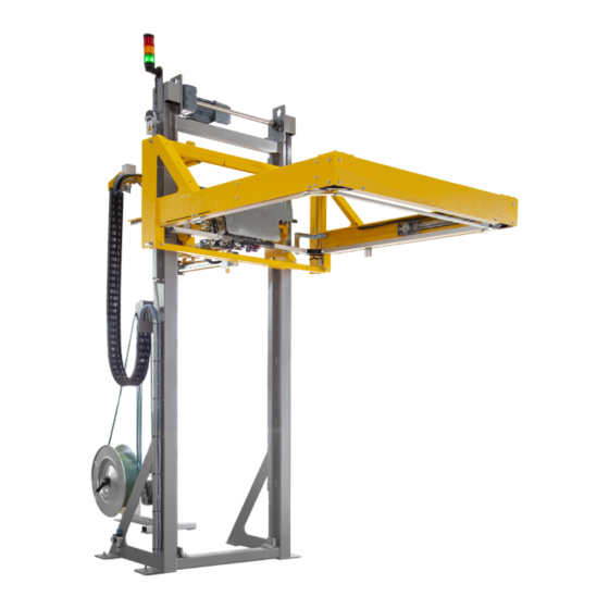
Page 8: Description
HSM 3000 DESCRIPTION Packages, barrels, building blocks, etc. can be 4.1 DESIGN strapped horizontally with this strapping machine. The machine consists of the following main assemblies Strapping can be divided into five main functions: (see Fig. 1). – plastic strap fed through strap guides – strapping head driven to package The description refers to a generally autho- –... -
Page 9: Machine Description
HSM 3000 Two limit switches interrupts the lowering motion of the 4.2 MASCHINE DESCRIPTION carriage immediately when actuated. The carriage then returns to its initial position and the control unit indi- a) Strapping head, type H 3000 cates a fault. -
Page 10: Operating Elements
HSM 3000 The components mounted on the desk cover are label- 4.2.1 OPERATING ELEMENTS led on the outside with the relevant function (pictogram) and inside the desk cover with the operating material With the exception of the enabling button, all positioning designation (BMK). The first two digits of the BMK... - Page 11 HSM 3000 Fig. 4 Touch screen (HMI) 10.19...
-
Page 12: Description Of Operating Sequence
HSM 3000 The following command section (3-layer enabling but- When the safety fence door is opened and the ton) is also connected by cable to the control desk: key switch on control desk turned, the machi- ne is automatically released for special operation with the enabling button. -
Page 13: Signal Exchange
HSM 3000 4.2.3 SIGNAL EXCHANGE 4.2.4 MODES OF OPERATION Signals from customer A difference is drawn between normal and special Electrical connection diagram page 33.0, operation: terminal stem X11. All signal inputs for strapping machines must – Normal operation be electrically isolated, respectively supplied with The machine is in normal operation when the packa- our control voltage 24 V DC terminal 1. -
Page 14: Installation And Putting Into Service
HSM 3000 INSTALLATION AND PUTTING INTO SERVICE 5.3 SIGNAL EXCHANGE 5.1 INSTALLATION Signal exchange with the control system of the con- Mechanical assembly of dismantled machines, con- nection of the electrical control unit and commissioning veyor unit must be provided in accordance with the... -
Page 15: Operating Instructions
HSM 3000 OPERATING INSTRUCTIONS 6.1 SWITCH ON/OFF MACHINE (MODE OF OPERATIONS) OPERATING ELEMENTS ACTIVITY/DESCRIPTION a) Starting Main switch Turn to position „1“ and wait until the CPU of the SPS is booted (waiting time max. 15 s). Operate. Select the desired mode on start screen. -
Page 16: Mode Of Operation „Manual
HSM 3000 6.2 MODE OF OPERATION „MANUAL“ OPERATING ELEMENTS ACTIVITY/DESCRIPTION Individual strapping head functions for head can be performed manually: – „Strap Feed/Take-up“ – „Strap Tensioning/Release“ – „Maintenance“ causes the pressure plate on the strapping head to open. This facilitates strap residue removal and strapping head cleaning. - Page 17 HSM 3000 OPERATING ELEMENTS ACTIVITY/DESCRIPTION Individual machine functions can be performed manu- ally: – „Lifting unit Upward / Downward“ Initial position „up“. – „Teach-In“ screen jump to teach-in. – „Setup“ screen jump to parameter settings. – (1) Push-button „Exit“ to return to the start screen.
-
Page 18: Teach-In
HSM 3000 ACTIVITY/DESCRIPTION OPERATING ELEMENTS Teach-In: To program strapping positions, see chapter 6.2.1. (1) Actuate Teach-In (2) Save strapping position (3) Delete all strapping positions (4) Selection of program (5) Strapping position stored = green light (6) Screen jump to positions. - Page 19 HSM 3000 6.2.1 UMREIFUNSPOSITIONEN PROGRAMMIEREN "TEACH-IN" OPERATING ELEMENTS ACTIVITY/DESCRIPTION Prerequisite: Lifting unit in upper initial position. a) Store strapping positions (from top to bottom) – On HMI side, select „Lifting unit“ and „Teach-in“ function. – Select the desired program (1) (25 or 99 Programs) –...
-
Page 20: Information Library
HSM 3000 6.3 INFORMATION LIBRARY OPERATING ELEMENTS ACTIVITY/DESCRIPTION Individual information can be obtained at the informati- on library under various submenus. – Buttons for the selection of various sub menus. – (1) Push-button „Exit“ to return to the start screen. - Page 21 HSM 3000 OPERATING ELEMENTS ACTIVITY/DESCRIPTION Factory settings: – Display of machine number – Display the circuit diagram number. – Display of date and time. – Strapping counter. – (1) Push-button „Exit“ to return to the start screen. Language: – Select language.
-
Page 22: Messages And Malfunctions
HSM 3000 6.4 MESSAGES AND MALFUNCTIONS ACTIVITY/DESCRIPTION OPERATING ELEMENTS Messages: Operating messages and malfunctions Communication signal exchange faulty (Manual, Cycle, Automatic, Information Library): Machine not in home position Selection is made by External 34 Control system off 35 EMERGENCY STOP actuated Safetydoor circuit not ok... -
Page 23: Working In Danger Area
HSM 3000 6.5.1 WORKING BELOW CARRIAGE 6.5 WORKING IN DANGER AREA It is sometimes necessary to open the door WARNING in the safety fence to eliminate faults from Refer to Chapter 6.5 when working in the the machine. When working in the danger area refer danger area. -
Page 24: Replace Strap Coil
HSM 3000 6.6 REPLACING STRAP COIL – Insert new coil so that the strap start is on top (see Fig. 5, center picture). When the fault indication „Out of strap“ – Mount dispenser disc with knurled nut. on touchscreen appears, there is practically no –... -
Page 25: Elimination Of Faults (Operator)
HSM 3000 6.7 ELIMINATION OF FAULTS (OPERATOR) 6.7.3 COLLISION GUARD Refer to Chapter 8.1 or to the operating instructions Symptoms H 3000 for faults not described in this section. – The strap guide ring cannot move down beyond the- package. The collision guard is actuated. The carri- age moves up and a fault indication is given. -
Page 26: Inverter Drive Malfunction
HSM 3000 6.7.4 INVERTER DRIVE MALFUNCTION 6.8 CHECK OF SEAL Symptoms – Regulary check the seal (see Fig. 6) for its appea- – The carriage (strapping unit) can not moved vertical- rance. ly. Fault indication is activated. Causes The straps must be sealed cleanly to obtain –... -
Page 27: Preventive Maintenance
HSM 3000 PREVENTIVE MAINTENANCE CAUTION Refer to the operating instructions H 3000 for maintenance and cleaning of the strap- When working in the danger area refer to ping head. Chapter 6.5. When working on normally live parts, the- ATTENTION main switch should be turned to position „0“... -
Page 28: Functional Checks Of Assemblies Affecting Safety
HSM 3000 c) „Control system start“ button 7.2 FUNCTIONAL CHECKS OF ASSEMBLIES – Open and reclose door of safety fence with button AFFECTING SAFETY pressed, then release button. • It must not be possible for any motors to start. CAUTION •... -
Page 29: Corrective Maintenance
HSM 3000 CORRECTIVE MAINTENANCE Only original spare parts must be used. When 8.2 SWIVEL STRAPPING HEAD 90° ordering spare parts we request a FAX trans- (SERVICE POSITION) mission of the relevant module parts list. We also require the machine number. This is shown on the main For maintenance and repair work on the parts list and on the nameplate.To localise faults we re-... -
Page 30: Replacing Strapping Head
HSM 3000 8.4 CHANGING STRAP QUALITY 8.3 REPLACING STRAPPING HEAD AND STRAP DIMENSIONS Removal a) Changing strap quality CAUTION Before definite change of strap quality or manufac- turer, tests should be run to determine the operating Refer to Chapter 6.5 when working in the safety of the machine with the new strap. -
Page 31: Ordering Spare Parts
HSM 3000 8.6 ORDERING SPARE PARTS To determine spare part number 1. Locate defective part 2. Open „Technical Documentation“ folder or start enclosed USB stick. Massbild Layout Déssin coté Betriebsanleitung, Ersatzteiliste Operating instruction, spare part list Mode d'emploi, liste des pièces de rechange Bandführungen... -
Page 32: Dismantling And Disposal
HSM 3000 DISMANTLING AND DISPOSAL When dismantling the machine appropriate attention The electrical assemblies should be dismantled so that should be paid to its size and the weight of the individu- the mechanical, electromechanical and electronic com- al parts. ponents can be disposed of separately.
Need help?
Do you have a question about the HSM 3000 and is the answer not in the manual?
Questions and answers