Advertisement
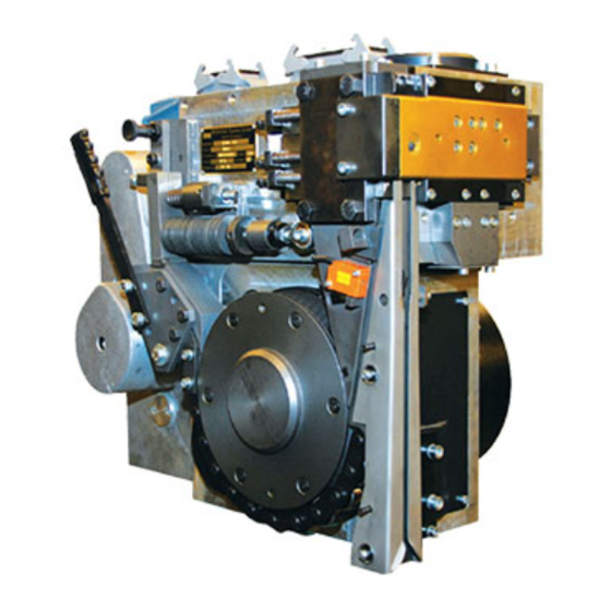
PLASTIC STRAPPING HEAD
MODEL AK200HDX-19 / 25 / 32 mm
Serial N° 09/2008 SN3627
As at : 28 March 2011
IMPORTANT!
DO NOT DESTROY
It is the customer's reponsibility to have all
operators and servicemen read and understand
this manual.
Contact your local Signode representative for
additional copies of this manual.
OPERATION, PARTS AND SAFETY MANUAL
Advertisement
Table of Contents

Related Manuals for Signode AK200HDX-19


Summary of Contents for Signode AK200HDX-19
- Page 1 PLASTIC STRAPPING HEAD MODEL AK200HDX-19 / 25 / 32 mm Serial N° 09/2008 SN3627 As at : 28 March 2011 IMPORTANT! DO NOT DESTROY It is the customer’s reponsibility to have all operators and servicemen read and understand this manual.
- Page 2 SIGNODE AK200-HDX Basic Operating and Adjustment Instructions Sealing punch polder Cam shaft Weld Motor Drive motor Disk washer Pusher with aux. spring (cover plate) Strap entry chute Sealing Mechanism Air blowing device Back-up roller chain Feed wheel Strap guide wedge...
-
Page 3: General Safety
GENERAL SAFETY This manual gives you information on how to operate and maintain your Signode Power Strapping Machine. Only trained personnel should operate or service machine. Read these safety instructions before operating or servicing your machine. OPERATING MACHINE SERVICING MACHINE BEFORE Read the operating instructions. - Page 4 1. Insert strap Important Caution! To prevent strap jams natural strap curl in the direction shown (with the curl up)! Disk Washers Strap Cam Shaft Wrench Back-up roller Chain Part No. 0460605 Release tension of the back-up roller chain by compressing the stack of disk washers with the cam shaft wrench.
- Page 5 2. Opening of pusher (by hand) Pusher (cover plate) Cam shaft wrench Part No.: 0460605 Insert the camshaft wrench into the hole at the end of the pusher lever and move it towards the right. The pusher opens and exposes the die holder and vibrator for inspection and cleaning.
- Page 6 Disengage back-up roller chain Cam shaft To clean the strap guide channel, to remove pieces of strap and to turn the cam shaft by hand, the back-up roller chain must be disengaged. First of all, release the back-up roller chain and pull out the pin. Then disengage the complete chute wedge with the chain.
- Page 7 Strap tension adjustment Adjustment screw Strap tension is increased by turning the adjustment screw clockwise and decreased by turning it counter-clockwise. If an extreme low strap tension is desired, you may reduce the disk washers and add on compression spring. Refer to your instruction manual under chapter "disk washer". (Drawing-No.
- Page 8 Function of the Proximity switch (strap Stop switch) Switch actuator B102 Proximity Switch “strap stop ” With no strap present, the strap Stop switch is not actuated. Strap passing the switch actuator pushes the same down, energizing the proximity switch (B102 Strap stop Proximity switch) Cam shaft position: 0...
- Page 9 5.1 Function of proximity switch B103 & B104 “ pusher open / closed” B103 Proximity switch "pusher open" Energized (diode lit) Pusher fully open Cam shaft position: 9 B104 Proximity switch "pusher closed" Energized (diode lit) Pusher closed Cam shaft position: 0...
- Page 10 Function of proximity switch B105 switching from high speed to slow speed tension Switching energized = high speed tensioning (diode lit) Cam shaft position: before 2 B105 Proximity switch "Pre-Tension reached" Not energized = slow tension Cam shaft position: behind 2 B105 Proximity switch "Pre-Tension reached"...
- Page 11 Function of proximity switch B106 switch for brake "final tension reached" Not energized = strap is being tensioned (slow) Cam shaft position: at 3 B106 Proximity switch "Final-tension reached" Energized (diode lit) = Strap tension is Cam shaft position: at B106 Proximity Switch "Final-tension reached"...
- Page 12 TENSION AND SEALING PROCEDURE Home position proximity switch B104 "shutter close" activated. Shutter closed. Tip of strap is clamped. Proximity switch B106 "max. strap tension reached" will be activated for the first time. Proximity switch B105 "Pre- tension reached" will be free Switching into tension slow speed.
- Page 13 SERVICE AND MAINTENANCE MANUAL FOR STRAPPING HEAD MODEL AK200-HDX-19 / 25 / 32 mm...
- Page 14 T A B L E O F C O N T E N T S Section Page General Technical Specifications Sequence of Operation Positions on Camshaft Display Preventive Maintenance Parts Removal and Replacement Head Adjustments Trouble Shooting Recommended Spare Parts List Remote Spare Parts List HDX auf 32 mm / 25 mm / 19 mm Conversion Kit AK200-...
- Page 15 GENERAL The SIGNODE AK200 Plastic Strapping Head is designed to be used for applying various qualities of plastic strapping fully automatically. The head is only part of the strapping installation, which consists of the main structure, chute system and control panel.
- Page 16 TECHNICAL SPECIFICATIONS AK200-HDX Strapping Width: 32 mm; 25 mm; 19 mm Strap Thickness: 0,5 - 1,3 mm Joint Strength: Depends on individual strap size and strap quality Feed and Take Up Rate: 1,25 m/sec. (high) 0,07 m/sec. (slow) Tension: max. 6000 N / adjustable Min.
-
Page 17: Sequence Of Operation
SEQUENCE OF OPERATION GENERAL The SIGNODE AK200-HDX is electrically powered and electrically / electronically controlled. Only one power source is needed to operate the head. The sequence of operation consists of two major functions. These are: - First "Strap Feeding"... - Page 18 Strapping head drive (allegory)
- Page 19 Table of contents See drawing M 24 Motor 464631, Rep. 82 See drawing M 28 Weld Motor 464631, Rep.83 Small clutch 15 Nm Y 37 « transmission Fast » Large clutch 60 Nm Y 22 « Transmission Slow » Electro-Magnetic Brake Y 36 "Strap Drive"...
- Page 20 Operation Description (See section 4, simplified view) The strapping head is in home position. The camshaft display indicator is on - 0 - position, and the camshaft is blocked against rotation in anti-clockwise direction further than the - 0 - position on the camshaft display.
- Page 21 Next step; strap tension will be initiated. The camshaft brake Y38 will now be activated and the brake Y36 is de-energised. The large clutch Y22 in the transmission is de-energised and the small clutch Y37 will be activated. The strap drive changes rotation at high speed and the strap is pulled out of the strap chute system and is applied around the package (during high tension the camshaft brake Y38 will be de-energised after a certain delayed time).
- Page 22 The camshaft rotates from position 5 to position 7 and the next step, welding will be initiated. Thereby the vibrator support moves forward with the cutter blade and vibrator. (see drwg. 464655, pos. 9, 22, 25, Page 39). At point 6 the sensor "Pre-tension reached" will be de-activated again. With this switching point the weld motor will be started, and via the eccentric drive of the vibrator the weld oscillation will be reached.
- Page 23 After the cool off time has expired, strap release will be initiated. The camshaft rotates from position 7 into point 8. Gripper, loop grip and vibrator move backwards to its home point 8. The camshaft rotates from point 8 without stopping into position 9. The shutter starts opening (sensor "Shutter close"...
- Page 24 4. POSITIONS ON THE CAMSHAFT DISPLAY Position 0: The strapping head is in home position. Camshaft brake Y38 holds the camshaft (time controlled) in position 0. The camshaft is blocked against turning in counter-clockwise direction further than 0 position via a freewheel. The proximity switch "Shutter Close"...
- Page 25 TENSION- AND SEALING PROCEDURE Home position proximity switch B104 "shutter close" activated. Shutter closed. Tip of strap is clamped. Proximity switch B106 "max. strap tension reached" will be activated for the first time. Proximity switch B105 "Pre- tension reached" will be free Switching into tension slow speed.
- Page 26 COMMENTS TO THE PLANETARY GEAR DRIVE (Strap Drive) The planetary gear drive on the strap drive has the following major function: It takes over the strap feeding in feeding direction. The feed wheel ring is driven via the solid shaft, drwg. 464626, pos. 2, page 47 and the planetary gears, pos. 10.
-
Page 27: Preventive Maintenance
5. PREVENTIVE MAINTENANCE Daily: - Clean feed wheel and chain by using an air pistol. - Shutter must be open to clean sealing mechanism, remove remaining weld scrap. - Check whether strap limit switch works free of trouble and the strap tail is clamped. (see section 7.2.) Weekly: - Check strap transportation, disconnect chain, check bearing and chain links, check feed... -
Page 28: Parts Removal And Replacement
PARTS REMOVAL AND REPLACEMENT Before you start with service please disconnect the chain. Remove release pin (see drwg. 464631, pos. 58) and swing strap guide wedge inclusive chain (see drwg. 464631, pos. 10, page 33) backwards. Also please swing out the stop device by pull off the catch pin 64643 Pos. - Page 29 To remove gripper "tip of strap" (see drwg. 464655, pos. 8, page 39) - Dismantle gripper as described under point 6.2 and 6.3. - Note, remove first vibrator incl. vibrator support before dismantling the gripper. To remove clutch Y37 from transmission (see drwg.
- Page 30 To remove cams from camshaft display (see drwg. 464613, page 33) - Remove release pin (see drwg. 464631, pos. 58, page 33).and swing back strap guide wedge with strap guide chain (see drwg. 464631, pos. 10, page 33). Also swing out the stop device.
-
Page 31: Head Adjustments
HEAD ADJUSTMENTS Re-adjustment of gripper, loop grip and vibrator are necessary if: 1. Cam levers are replaced. 2. Adjustment screws are replaced. 3. Gripper, loop grip or vibrator support are replaced. Re-adjustment must be carried out as follows: To begin with, set the adjustment screw for each setting according to the table "Normal setting of the adjustment screw length AK200". - Page 32 Because of the high resistance from the tension cam it is not possible to turn the camshaft by hand. If it necessary to turn the camshaft by hand, please disconnected first the strap guide chain. Remove the release pin (see drawing 0464631 Pos. 58, page 33) and swing strap guide wedge inclusive chain (see drawing 0464631 Pos.
- Page 33 Additional time values stored in the program sequence for head function control must be changed only by a Signode service engineer. Adjustment of strap tension The spring assembly (see drwg. 464631, pos. 9, page 33) permits the variation or adjustment of the strap tension.
-
Page 34: Troubleshooting
TROUBLE SHOOTING 8.00 OPERATIONAL DIFFICULTIES DURING STRAP FEEDING S Y M P T O M C A U S E R E M E D Y 8.01 Incomplete or improper strap feed. Strap feed disturbance into the head. Inspect dispenser, accumulator and pulleys etc. - Page 35 8.10 OPERATIONAL DIFFICULTIES DURING STRAP TAKE-UP S Y M P T O M C A U S E R E M E D Y 8.11 Strap is fed backwards out of the strap drive, Tip of strap did not enter its end position. Timing must be changed by reprogramming while the camshaft stops between points 1 and 2.
- Page 36 8.20 OPERATIONAL DIFFICULTIES DURING STRAP TENSION S Y M P T O M C A U S E R E M E D Y 8.21 The strap drive does not move, there is a Large clutch Y22 in transmission is worn out. Exchange transmission, see section 6.6 of the squeaking noise and the camshaft stops shortly manual.
- Page 37 8.30 OPERATIONAL DIFFICULTIES DURING "SEALING AND CUT-OFF" S Y M P T O M C A U S E R E M E D Y 8.31 The strap is taken up slowly while the Brake Y38 is not activated. Check the switch B106 "max. strap tension". camshaft stops between points 5 and 6.
- Page 38 S Y M P T O M C A U S E R E M E D Y 8.36 No exact weld joint. Insufficient vibrator contact pressure. Readjust contact pressure, see section 7.0/7.1. Eccenter drive for vibrator defect. Check motor M28 connection terminal. Check brushes for weld motor.M28 Check bolt for eccentric arm (see drwg.
- Page 39 9. RECOMMENDED SPARE PARTS LIST AK200-HDX-32 MM Part-no: 0464690 Sub-assembly seal mechanism Pos. in Pos. Qty. Description Part N° . Sub-Ass'y. Shutter complete 464660 Loop grip, complete 464676 Gripper, complete 464669 Vibrator 464677 Vibrator bolt 464233 INA-Flat cage needle roll FF 2010 464228 Eccenter arm bolt 464371...
- Page 40 9. RECOMMENDED SPARE PARTS LIST AK200-HDX-25 MM Part-no: 0464691 Sub-assembly seal mechanism Pos. in Pos. Qty. Description Part N° . Sub-Ass'y. Shutter complete 464660 Loop grip, complete 464676 Gripper, complete 464669 Vibrator 464677 Vibrator bolt 464233 INA-Flat cage needle roll FF 2010 464228 Eccenter arm bolt 464371...
- Page 41 9. Recommended spare parts list AK200-HDX-19 mm Part-no: 0464692 Sub-assembly seal mechanism Pos. in Pos. Qty. Description Part N° . Sub-Ass'y. Shutter complete 464660 Loop grip, complete 464676 Gripper, complete 464669 Vibrator 464677 Vibrator bolt 464233 INA-Flat cage needle roll FF 2010 464228 Eccenter arm bolt 464371...
- Page 42 10. REMOTE SPARE PARTS LIST AK200-HDX-32 mm Part-no 464693 Assembly Head Pos. in Pos. Qty. Description Part N° . Sub-Ass'y. Cam follower KR 19 PP 464289 DU-Bushing 2515 DU 463382 Roller version 1 463377 Pin version 1 463378 Bolt lock 461097 Countersunk screw M4x6 DIN 7991 462105...
- Page 43 10. REMOTE SPARE PARTS LIST AK200- HDX-25 Part-no 464694 Assembly Head Pos. in Pos. Qty. Description Part N° . Sub-Ass'y. Cam follower KR 19 PP 464289 DU-Bushing 2515 DU 463382 Roller version 1 463377 Pin version 1 463378 Bolt lock 461097 Countersunk screw M4x6 DIN 7991 462105...
- Page 44 10. REMOTE SPARE PARTS LIST AK200- HDX-19 Part-no 464695 Assembly Head Pos. in Pos. Qty. Description Part N° . Sub-Ass'y. Cam follower KR 19 PP 464289 DU-Bushing 2515 DU 463382 Roller version 1 463377 Pin version 1 463378 Bolt lock 461097 Countersunk screw M4x6 DIN 7991 462105...
- Page 45 CONVERSION KIT to AK200-HDX-32 Part-no 464696 Pos. in Qty. Description Part N° . Sub-Ass'y. Segment AK200-32 464648 Page 33 Strap guide wedge AK200-32 compl. 464682 Page 39 Strap guide wedge AK200-32 compl. 464636 Page 33 Guide AK200-32 464678 Page 39 Spacer 464683 Page 39...
- Page 46 11. SUB-ASSEMBLY DRAWINGS & PARTS LIST Page 464631 vers. 32 mm Strapping Head 464624 vers. 25 mm 464618 vers. 19 mm 464655 vers. 32 mm Sealing Mechanism 464656 vers. 25 mm 464657 vers. 19 mm Transmission - 15 - 100.36 Strap Drive 464626 Brake...
-
Page 48: Parts List
PARTS LIST Description: Strapping head AK200-HDX Drawing N° : 464631 Version/Part-No.: 32 mm strap size 464631 25 mm strap size 464624 strap size 19 mm 464618 Pos. Qty. Description Drawing N° . DIN/Version Part N° . Housing 464600 Version 32 mm 464626 Sub Assy. - Page 49 PARTS LIST Description: Strapping head AK200-HDX Drawing N° .: 464631 Version/Part-No.: 32 mm strap size 464631 25 mm strap size 464624 strap size 19 mm 464618 Pos. Qty. Description Drawing N° . DIN/Version Part N° . Soc. head cap screw M8x20 0WT0856 Hex.
- Page 50 PARTS LIST Description: Strapping head AK200-HDX Drawing N° : 464631 Version/Part-No.: 32 mm strap size 464631 25 mm strap size 464624 strap size 19 mm 464618 Pos. Qty. Description Drawing N° . DIN/Version Part N° . Soc. head cap screw M3x16 0WT0805 Collar...
- Page 51 PARTS LIST Description: Strapping head AK200-HDX Drawing N° : 464631 Version/Part N° : 32 mm strap size 464631 25 mm strap size 464624 strap size 19 mm 464618 Pos. Qty. Description Drawing N° . DIN/Version Part N° . Proximity switch „Final tension 461764 reached“...
- Page 52 PARTS LIST Description: Strapping head AK200-HDX Drawing N° : 464631 Version/Part N° : 32 mm strap size 464631 25 mm strap size 464624 strap size 19 mm 464618 Pos. Qty. Description Drawing N° . DIN/Version Part N° . Spring retainer 072400 Spring retainer 040460...
- Page 53 Adjustment after inserting of Belleville washers and fitting bolt key 74 tightened up to limit strap Proper arrangement for Belleville washers: 4 pcs. spring kits of 6 each Adjustment after inserting of Belleville washers and fitting bolt key 74 tightened up to limit strap Proper arrangement for Belleville washers: 6 pcs.
- Page 54 39 b...
- Page 55 PARTS LIST Description: Sealing mechanism AK200-HDX Drawing N° : 464655 Version/Part N° : 32 mm strap size 464655 25 mm strap size 464656 strap size 19 mm 464657 Pos. Qty. Description Drawing N° . DIN/Version Part N° . Shutter, complete Version 32 464660 Upper guide rail...
- Page 56 PARTS LIST Description: Sealing mechanism AK200-HDX Drawing N° : 464655 Version/Part N° : 32 mm strap size 464655 25 mm strap size 464656 strap size 19 mm 464657 Pos. Qty. Description Drawing-No. DIN/Version Part-No. Pressure spring KM-3235 120 lg 464686 6x24 6325 0WT2512...
- Page 57 PARTS LIST Description: Sealing mechanism AK200-HDX Drawing N° : 464655 Version/Part N° : 32 mm strap size 464655 25 mm strap size 464656 strap size 19 mm 464657 Pos. Qty. Description Drawing N° . DIN/Version Part N° . Version 32 mm 464679 464684 25 mm...
- Page 58 Insert these screws with loctite If for any reason the transmission will be opened, never oil or grease parts. It will destroy the function of the clutch Transmission 100.36...
- Page 59 PARTS LIST Description: Transmission AK200-HDX Drawing N° : 100.36 Version: 15 mm pulley Part N° : 462953 in exchange Part-No.: 462954 Pos. Qty. Description Drawing N° . DIN/Version Part N° . Housing 100.06-001 461622 Shaft 100.36-002 462847 Gear 100.06-004 460619 Gear 100.06-006 460622...
- Page 60 PARTS LIST Description: Transmission AK200-HDX Drawing N° : 100.36 Version: 15 mm pulley Part N° : 462953 in exchange Part-No.: 462954 Pos. Qty. Description Drawing N° . DIN/Version Part N° . Lock ring, extern 30x1,5 0WT2826 Lock ring, intern 62x2 0WT2939 Lock ring, extern 40x1,75...
- Page 61 PARTS LIST Description: Transmission AK200-HDX Drawing N° : 100.36 Version: 15 mm pulley Part N° : 462953 in exchange Part-No.: 462954 Pos. Qty. Description Drawing N° . DIN/Version Part N° . Hub and gear, complete Version 15 462949 Belt pulley 100.10-043 462848 Conical element...
- Page 62 If you exchange the feed wheel ring please exchange the 6 pcs. soc. hd. cap screw also. 6 pcs. soc. hd. cap screw property class 10.9 must be tightened symmetrically by 35 Nm turning moment. Strap drive AK200HDX 464626...
- Page 63 PARTS LIST Description: Strap drive AK200-HDX Drawing N° : 464626 Version/Part N° : 32 mm strap size 464626 25 mm strap size 464627 strap size 19 mm 464628 Pos. Qty. Description Drawing N° . DIN/Version Part N° . Planetary gear shaft 100.03-001 464491 Shaft with gear...
- Page 64 PARTS LIST Description: Strap drive AK200-HDX Drawing N° : 464626 Version/Part N° : 32 mm strap size 464626 25 mm strap size 464627 strap size 19 mm 464628 Pos. Qty. Description Drawing N° . DIN/Version Part N° . Lock ring 17x1 0WT2815 Lock ring...
- Page 65 Insert these screws Strap center with loctite Brake 100.14...
- Page 66 PARTS LIST Description: Brake AK200-HDX Drawing N° : 100.14 Version/Part N° : 462459 (Part No. for complete list) Pos. Qty. Description Drawing N° . DIN/Version Part N° . Pinion shaft 100.14-001 462460 Ball bearing 6208-2RS 462461 Washer 40x50x2 462140 A12x8x67 6885 462466 Carrier-hub...
- Page 67 Intermediate shaft 464291...
- Page 68 PARTS LIST Description: Intermediate AK200-HDX-19/25 Drawing N° : 464291 Version/Part N° : 464291 Pos. Qty. Description Drawing N° . DIN/Version Part N° . Shaft with involute connection 462966 Cover 150.14-002 462546 Soc. head cap screw M6x20 0WT0841 Spacer 100.05-004 462034 Lock washer 7980 0WT2256...
- Page 69 Note: When exchanging the cams, please note that the imprinted number points towards in the conical gear wheel of 4 each Insert these screws with loctite Camshaft 464613...
- Page 70 PARTS LIST Description: Camshaft AK200-HDX Drawing N° : 4644613 Version/Part N° : AK200-HDX-HT/2 464613 Pos. Qty. Description Drawing N° . DIN/Version Part N° . Shaft 462964 Cover 100.04-002 460582 Cover 100.04-003 460584 200.7/MT 464335* Actuator disc „Final tension B106 464397 reached“...
- Page 71 Strap drive pos. 9 necessary clearance Insert these screws with loctite Brake "Camshaft turn" 150.15...
- Page 72 PARTS LIST Description: Camshaft brake AK200-HDX Drawing N° : 150.15 Version/Part N° : 462840 Pos. Qty. Description Drawing N° . DIN/Version Part N° . Axle with gear 463314 Bearing bock 150.15-003 462837 Mounting plate 150.15-004 462838 Lock ring, intern 0WT2922 Ball bearing 6002 2RS 462955...
- Page 73 Note: Apply normal commercial grease to the shaft after approx. 20.000 strap cycles (or after 1 month) 5 mm - 6 mm Spring stroke with strap being inserted Insert these screws with loctite Mark these screw position with sealing wax Spring assembly 100.07...
- Page 74 PARTS LIST Description: Spring assembly AK200-HDX-19/25 Drawing N° : 100.07 soft Version/Part N° : 462809 Pos. Qty. Description Drawing N° . DIN/Version Part N° . Guide shaft 100.07-001 460648 Sleeve 100.07-002 460649 Spring sleeve 100.07-003 460650 Adjustment nut 100.07-004 460653 Spacer 100.07-005 460654...
- Page 75 Adjustment test, without strap in head clearance between pos. 4 and pos. 7 approx. 1mm. Readjust during wear of feed wheel ring. Attention! When adjusting compression spring do not risk any strap deformation Reduce pre-tension of compr. Spring pos. 7 after exchange of feed wheel ring, so that clearance of 1 mm is provided...
- Page 76 PARTS LIST Description: Insert guide with spring AK200-HDX Drawing N° : 464643 Version/Part N° : 32 mm strap size 464643 25 mm strap size 464644 19 mm strap size 464645 Pos. Qty. Description Drawing N° . DIN/Version Part N° . 464646 Plate front 100.09-002...
- Page 77 Insert guide wedge 464636...
- Page 78 PARTS LIST Description: Strap guide wedge AK200-HDX Drawing N° : 464636 Version/Part N° : 32 mm strap size 464636 25 mm strap size 464665 19 mm strap size 464310 Pos. Qty. Description Drawing N° . DIN/Version Part N° . 464637 Version 32 mm 464460 Strap guide wedge...
- Page 79 PARTS LIST Description: Air blowing device Drawing N° : 464263 Version/Part N° : 464269 Pos. Qty. Description Drawing N° . DIN/Version Part N° . Fitting SCK600-K 460279 Tube 462934 Mounting for tube 462933 Sleeve 1/8“ 464401 Seal ring KF 18 1/8“ 460190 Plastic hose PL-600, 750 lg.
- Page 82 2011/03/28 Furtm. Page. 42/ Pos. 63 Nr. 464230 Nr.464659 ( M. Funck ) 2010/09/02 JMM Up dated all pages and page 31 + Pos.9 2010/08/24 Hunecken Page 2,8,13,28,29,30,31,34,38,42,47,48,54+56 2009/01/29 Supper Original Version Rev. Date Name Description...
Need help?
Do you have a question about the AK200HDX-19 and is the answer not in the manual?
Questions and answers