Advertisement
Advertisement

Related Manuals for Kemppi PROMIG EVOLUTION 501


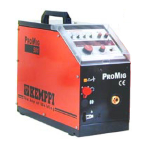
Summary of Contents for Kemppi PROMIG EVOLUTION 501
- Page 1 TECHNICAL MANUAL FOR PROMIG EVOLUTION 501, 501L, 511 & 530 (version 1.0)
-
Page 2: Table Of Contents
Contents Topic Page General maintenance Control card A001 4 - 14 ProSync 50 15 - 16 Troubleshooting 17 - 19 Measurements 20 - 29 Main circuit diagrams 30 - 31 Notes... -
Page 3: General Maintenance
• Function testing • Test welding NOTE ! Only person who have electrical engineering competence (fulfil the requirements of local laws and rules) and trained by Kemppi Oy is allowed to make maintenance and possible reparations for Kemppi -products. -
Page 4: Control Card A001
Control card A001 Layout EPROM D4... - Page 5 Control card A001 LED indicators • H1: CONTROL CARD POWER SOURCE OPERATION. Indicates the functioning of control card´s power source section. • H2: REMOTE CONTROLLER VOLTAGE. Indicates the presence of +5 Volts in the remote control circuit. If the LED is off there is a short circuit in the remote control circuit.
- Page 6 Control card A001 Jumper functions (jumper block X7) Factory setting 8 9 10 8 9 10 Wire feeder 1 (address 102) Wire feeder 2 (address 105) 8 9 10 8 9 10 Wire feeder 3 (address 150) Wire feeder 4 (address 153) 8 9 10...
- Page 7 Control card A001 Jumper functions (jumper block X7) Gas/Water cooled gun selection switch by- 8 9 10 passing (always in water position). Gas/Water cooled gun selection switch by- 8 9 10 passing (selection controlled by Gas/Water selection switch). Output is linear according to potentiometer X7 1 2 8 9 10 turning angle.
- Page 8 Control card A001 Jumper functions (jumper block X7) Local control function is switched on 1 2 3 4 8 9 10 automatically, when remote controller is disconnected. Remote control function stays on, when remote X7 1 2 8 9 10 controller is disconnected.
- Page 9 Control card A001 Jumper functions (jumper block X7) 1 2 3 4 Fe synergic MIG / PULSMIG (ML –panel). AlSi synergic MIG / PULSMIG (ML –panel, X7 1 2 extra sticker). X7 1 2 Wire feeding max. speed 18 m. / min. X7 1 2 Wire feeding max.
- Page 10 Control card A001 Jumper functions (jumper block X10 “software selection”) Promig Evolution software Promig software Promig INOX software Promig Opel special software...
- Page 11 Control card A001 Error codes Error 1: • MMA/2T/4T -selection switch is turned into MMA position when source is already welding with another method (MMA local control from power source or from TIG). • MMA/2T/4T -selection switch is turned into MMA position and there is malfunction in connection between power source and wire feeder (intermediate cable or connectors).
- Page 12 Control card A001 Error codes Error 8: • PMT torch has overheated. This function can be disabled by removing jumper 5 when using standard MIG guns (without RMT-10 and overheat protection facilities). Error 9: • Overload of wire feed motor. Error 10: •...
- Page 13 Control card A001 Error codes Error 14: • Wire feeder supply voltage >70 VDC Error codes removal • Error code Error 1 is removed, when Promig Evolution feeder is set to MIG mode. • Error code Error 2…4 is automatically removed in 5s, if the trigger is not pulled.
- Page 14 Control card A001 Arc ON/OFF -signal Arc on/off-signal can be used to control for example mechanization devices ON/OFF.
-
Page 15: Prosync
Prosync 50 (6263121) Mounting instruction • Install synchronisation card A002 (Prosync 50) to the Promig. See next page. • Install connector XW501 (“military-type”) to the machines front panel. Use 3,5 x 9,5 mm. screws (included to the delivery). • Connect connector XW502 (6-pole) from the XW501 to the connector X2 on the synchronisation card A002. - Page 16 Prosync 50 (6263121)
-
Page 17: Troubleshooting
Troubleshooting PROBLEM POSSIBLE CAUSE REMEDY The Promig Evolution Fuse F2 6,3A in the Change the fuse and doesn't work at all. Wire power source is blown. check that there are not feeding motor or any short circuits in solenoid valve is not control cable. - Page 18 Troubleshooting PROBLEM POSSIBLE CAUSE REMEDY The wire feeding motor Start line wires are cross Locate the cross M001 does not start, connected. connection to the MIG when MIG gun switch is gun or to the Promig pressed. Evolution and correct it. Wire feeding can not be Start line wires are cross Locate the cross...
- Page 19 Troubleshooting PROBLEM POSSIBLE CAUSE REMEDY Welding is breaking Short circuit between Check is there galvanic when the welding wire is cables inside of the torch. connection between touching the piece. welding current cable and start lines. Repair or replace cables if galvanic connection exist.
-
Page 20: Measurements
Measurements Wire feed motor M001 control (1) Wire feed speed: 1 m/min Wire feed motor control Wire feed speed: 1 m/min : 57 V peak : 2,26 V average Frequency: approx. 11 000 Hz... - Page 21 Measurements Wire feed motor M001 control (1) Wire feed speed: 8 m/min Wire feed motor control Wire feed speed: 8 m/min : 57 V peak : 11,22 V average Frequency: approx. 40 000 Hz...
- Page 22 Measurements Wire feed motor M001 control (1) Wire feed speed: 18 m/min Wire feed motor control Wire feed speed: 18 m/min : 57 V peak : 23,50 V average Frequency: approx. 40 000 Hz...
- Page 23 Measurements Solenoid valve Y001 control (2)
- Page 24 Measurements Remote controller connector (3) Remote controller, max Remote controller, min No remote controller...
- Page 25 Measurements MIG gun connection (4) PMT-gun connected : 11,9 V : -13,3 V MT-gun connected : 16,4 V : -13,3 V...
- Page 26 Measurements MIG gun connection (4) PMT-gun / start : 4,9 V : -12,8 V MT-gun / start...
- Page 27 Measurements MIG gun connection (4) PMT-gun RMT-10 pos. 1 : 11,1 V : -0,4 V PMT-gun RMT-10 pos. 1 + start : 4,9 V : -1,3 V...
- Page 28 Measurements MIG gun connection (4) PMT-gun RMT-10 pos. 3 : 11,1 V : -6,6 V PMT-gun RMT-10 pos. 3 + start : 4,4 V : -6,6 V...
- Page 29 Measurements MIG gun connection (4) PMT-gun RMT-10 pos. 5 : 11,5 V : -8,4 V PMT-gun RMT-10 pos. 5 + start : 4,4 V : -8,4 V...
-
Page 32: Notes
Notes...
Need help?
Do you have a question about the PROMIG EVOLUTION 501 and is the answer not in the manual?
Questions and answers