
Related Manuals for Danfoss 45 E Frame Series


Summary of Contents for Danfoss 45 E Frame Series
- Page 1 All manuals and user guides at all-guides.com Service Manual Open Circuit Axial Piston Pumps Series 45 E Frame powersolutions.danfoss.com...
- Page 2 Added displacement limiter adjustments 0301 August 2015 Danfoss Layout 0300 October 2012 add new control types November 2010 new last page February 2010 fix Osaka address March 2008 add displacement limiter specs March 2005 First edition © Danfoss | September 2016 AX00000024en-US0401...
-
Page 3: Table Of Contents
Introduction Overview......................................5 Safety precautions....................................5 Unintended machine movement............................5 Flammable cleaning solvents..............................5 Fluid under pressure.................................. 5 Personal safety..................................... 5 Symbols used in Danfoss literature............................6 General description..................................7 System circuit.....................................8 Technical specifications General specifications..................................9 Type of mounting..................................9 Auxiliary mounting pad options............................9 Control options....................................9... - Page 4 LS and PC Controls..................................30 Disassembly....................................30 Inspection....................................31 Reassembly....................................32 Electric Controls....................................34 Disassembly....................................34 Inspection....................................34 Reassembly....................................35 Electronic Torque Limiting Control............................36 Repair......................................36 Angle Sensor....................................37 Removal......................................37 Inspection....................................37 Reassembly....................................38 Servo Control Orifice..................................39 Plug and fitting sizes and torques............................40 © Danfoss | September 2016 AX00000024en-US0401...
-
Page 5: Overview
ASC. Danfoss ASCs are trained by the factory and certified on a regular basis. You can locate your nearest ASC using the distributor locator at www.powersolutions.danfoss.com Safety precautions Always consider safety precautions before beginning a service procedure. -
Page 6: Symbols Used In Danfoss Literature
All manuals and user guides at all-guides.com Service Manual Series 45 E Frame Open Circuit Pumps Introduction Symbols used in Danfoss literature WARNING may result in injury Tip, helpful suggestion CAUTION may result in damage to product or Lubricate with hydraulic fluid... -
Page 7: General Description
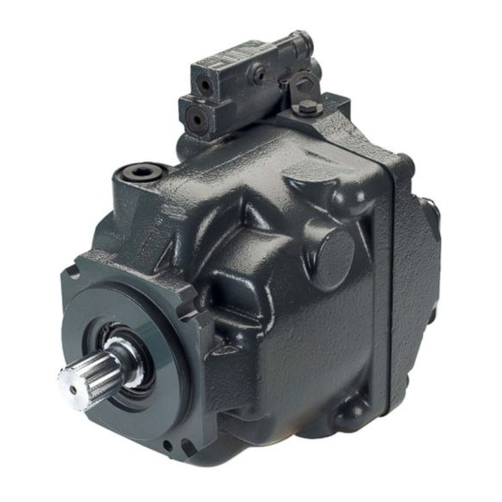
Introduction General description Danfoss Series 45 E frame open circuit piston pumps convert input torque into hydraulic power. Rotational force is transmitted through the input shaft to the cylinder block. The input shaft is supported by tapered roller bearings at the front and rear of the pump and is splined into the cylinder block . A lip- seal at the front end of the pump prevents leakage where the shaft exits the pump housing. -
Page 8: System Circuit
PVG 32 multi-section load sensing control valve Bi-directional gear motor System pressure Servo pressure Heat exchanger Actuator pressure Filter Reservoir Load sense pressure Actuator return Suction / case drain / system return P104 045E © Danfoss | September 2016 AX00000024en-US0401... -
Page 9: Technical Specifications
Clockwise, Counterclockwise Mounting SAE-C Auxiliary mounting SAE-A, SAE-B, SAE-BB, SAE-C, SAE-CC System ports (type) 4-bolt split flange System ports (location) Axial, Radial Control types PC, Remote PC, LS, LS with internal bleed © Danfoss | September 2016 AX00000024en-US0401 | 9... - Page 10 6779 [60 000] (1) Input speeds are valid at 1 bar absolute [0 in Hg vac] inlet pressure. See Inlet pressure vs. speed charts in the Series 45 Technical Information Manual 520L0519. 10 | © Danfoss | September 2016 AX00000024en-US0401...
-
Page 11: Hydraulic Parameters
(cold start) 1000 [4700] Filtration Required cleanliness level: ISO 4406 Class 18/13 or better. Refer to Danfoss publications Fluids and Filtration BLN-9887 or 520L0463 and Design Guidelines for Selecting and Maintaining the Required Hydraulic Fluid Cleanliness 520L0465. See Fluid and Filter Maintenance on page 20 for recommended fluid and filter change intervals. -
Page 12: Features
Since the auxiliary pad operates under case pressure, you must use an O-ring to seal the auxiliary pump mounting flange to the pad. Oil from the main pump case lubricates the drive coupling. For details refer to Series 45 Axial Piston Open Circuit Pumps Technical Information 520L0519. 12 | © Danfoss | September 2016 AX00000024en-US0401... -
Page 13: Input Shafts
When system pressure drops below the PC setting, the PC spring shifts the spool in the opposite © Danfoss | September 2016 AX00000024en-US0401 | 13... -
Page 14: Ls Control
LS spool with the servo piston and porting system pressure to the servo piston causing the pump to destroke. Typical load-sensing control valve Load Return pressure pressure Tank Load sense System P101 665E pressure pressure 14 | © Danfoss | September 2016 AX00000024en-US0401... -
Page 15: Electric Proportional Controls
LS spool shifts to port system pressure to servo piston Electric Proportional Controls Plus+1 Compliance All Series 45 Electric controls have met and passed the Danfoss PLUS+1 ® compliance standard testing, and as such, this Series 45 control is PLUS+1 ®... -
Page 16: Electronic Torque Limiting Controls (Etl)
“On”, or the Pressure Compensation pressure setting when “Off”. Electronic Torque Limiting Controls (ETL) PLUS+1 Compliance ® All Series 45 Electric controls have met and passed the Danfoss PLUS+1 ® compliance standard testing, and as such, this Series 45 control is PLUS+1 ®... - Page 17 PRV to result in a constant torque limit. Pump outlet pressure is equal to the load sense pressure, which is limited with the PRV, plus the margin pressure setting of the pump. © Danfoss | September 2016 AX00000024en-US0401 | 17...
-
Page 18: Pressure Measurement
L1, L2 = Case drain lines = Load sensing pressure port = CW endcap system pressure gauge* = Gauge port for port B* = Gauge port — servo pressure *Same pressure P104 052 18 | © Danfoss | September 2016 AX00000024en-US0401... -
Page 19: Initial Start-Up Procedures
10. Shut down the prime mover and remove the pressure gauge. Replace the plug at the system pressure gauge port. 11. Check the fluid level in the reservoir; add clean filtered fluid if necessary. The pump is now ready for operation. © Danfoss | September 2016 AX00000024en-US0401 | 19... -
Page 20: Fluid And Filter Maintenance
Change filters whenever the fluid is changed or when the filter indicator shows that it is necessary to change the filter. Replace all fluid lost during filter change. Fluid and filter change interval Reservoir type Maximum change interval Sealed 2000 hours Breather 500 hours 20 | © Danfoss | September 2016 AX00000024en-US0401... -
Page 21: Troubleshooting
Clean, repair, or replace heat exchanger as air temperature for the heat exchanger. or undersized heat exchanges will not meet required. Verify proper size of heat exchanger. cooling demands of the system. © Danfoss | September 2016 AX00000024en-US0401 | 21... -
Page 22: Low Pump Output Flow
Relief valve setting must be above PC setting to operate properly. Check external relief valve. Chattering external relief valve may cause Adjust or replace relief valve. unstable feedback to pump control. 22 | © Danfoss | September 2016 AX00000024en-US0401... -
Page 23: System Pressure Not Reaching Pc Setting
Hydraulic fluid viscosity above acceptable limits. High fluid viscosity causes high inlet vacuum. Select fluid with appropriate viscosity for expected operating temperature. See Hydraulic Fluids and Lubricants Technical Information Manual, 520L0463. © Danfoss | September 2016 AX00000024en-US0401 | 23... -
Page 24: Pc Control
LS adjustment LS, LD, LB, LE, PC, RP 42 bar/rev [609 PSI/rev] 17.2 bar/rev [250 PSI/rev] BB, BC, BP, BS 36 bar/rev [534 PSI/rev] AB, AC, AD, AJ, AS 8.5 bar/rev [123 PSI/rev] 24 | © Danfoss | September 2016 AX00000024en-US0401... - Page 25 0 - 10 bar [0 - 145 psi] 7/8-14 54 - 136 N•m [40 - 100 lbf•ft] Gauge M2 0 - 300 bar [0 - 4351 psi] 9/16-28 34-68 N•m [25-50 lbf•ft] P104053 © Danfoss | September 2016 AX00000024en-US0401 | 25...
-
Page 26: Ls Control
(2) PC setting is referenced to case pressure. Subtract case pressure from system pressure to compute the actual setting. 7. While holding the position of the PC adjusting plug, torque the PC set screw to 9.5 N•m [7 lbf•ft]. 26 | © Danfoss | September 2016 AX00000024en-US0401... -
Page 27: Displacement Limiters
70 to 130 cm³ [4.27 to 7.93 in³] E147C 87 to 147 cm³ [5.31 to 8.97 in³] Displacement per turn E100B 8.4 cm³/rev [0.51 in³/rev] E130B 8.4 cm³/rev [0.51 in³/rev] E147C 8.4 cm³/rev [0.51 in³/rev] © Danfoss | September 2016 AX00000024en-US0401 | 27... - Page 28 All manuals and user guides at all-guides.com Service Manual Series 45 E Frame Open Circuit Pumps Adjustments Displacement limiter cross-section P104 003 Dimensions [11.969] 302.7 max. [11.92] P108 470E 28 | © Danfoss | September 2016 AX00000024en-US0401...
-
Page 29: Minor Repair
Press the seal into the housing only far enough to clear the retaining ring groove. 4. Using the appropriate snap ring pliers, install the seal retaining ring. 5. Remove the installation sleeve. © Danfoss | September 2016 AX00000024en-US0401 | 29... -
Page 30: Auxiliary Pads
(J131) and torque to 37 - 50 N•m [27 - 37 lbf•ft]. LS and PC Controls Disassembly 1. Remove the 4 screws (C300) holding the control housing onto the end cap. 30 | © Danfoss | September 2016 AX00000024en-US0401... -
Page 31: Inspection
LS control shown; parts C104 through C106 and C112 through C118 are not used on PC control Inspection 1. Inspect the adjusting plugs for wear at the tips and where they contact the springs; replace as necessary. © Danfoss | September 2016 AX00000024en-US0401 | 31... -
Page 32: Reassembly
7. Install the control assembly onto the endcap using the 4 screws (C300). Torque the screws to 5.4 - 7.5 N•m [4 - 5.5 lbf•ft]. Torque screws in a criss-cross pattern and re-torque the first screw to ensure proper torque retention. 32 | © Danfoss | September 2016 AX00000024en-US0401... - Page 33 5.4 - 7.5 N•m C114 [4 - 5.5 lbf•ft] C134 C118B C138A C118A C138 C118B C118 E101226 LS control shown; parts C104 through C106 and C112 through C118 are not used on PC control © Danfoss | September 2016 AX00000024en-US0401 | 33...
-
Page 34: Electric Controls
5. Remove debris from orifices if necessary. Ensure the servo control orifice backup plug is clean, and remove debris if necessary. 6. Clean all parts and lubricate spools, springs, guides and new O-rings with clean hydraulic fluid. 34 | © Danfoss | September 2016 AX00000024en-US0401... -
Page 35: Reassembly
14. Install the control assembly onto the endcap using the four screws (C300). Torque the screws to 5.4 - 7.5 N•m [4 - 5.5 lbf•ft]. Torque screws in a criss-cross pattern and re-torque the first screw to ensure proper torque retention. 15. Check and adjust the control setting. See Adjustments. © Danfoss | September 2016 AX00000024en-US0401 | 35... -
Page 36: Electronic Torque Limiting Control
O-rings C300 Screws 6.4 Nm [4.7 lbf-ft] QC120 O-rings QC125 8.7 Nm [6.4 lbf-ft] QC150 Valve assembly 27.7 Nm [20.4 lbf-ft] H020 Manifold orifice 3 mm internal hex 2.7 Nm [24 in-lb} 36 | © Danfoss | September 2016 AX00000024en-US0401... -
Page 37: Angle Sensor
2. Check the angle sensor connector for breaks, pin deformation, or contamination. 3. Check sensor wiring for heat damage, scuffing/chafing, or kinks. 4. Check sensor seal area for contamination and surface damage © Danfoss | September 2016 AX00000024en-US0401 | 37... -
Page 38: Reassembly
3. Lubricate new O-ring (K175) with petroleum jelly. Install the O-ring to the angle sensor housing (K265) first. 4. Install angle sensor housing (K265) with O-ring (K175) to housing with 4 screws (K195) and torque to 5.9 Nm [4.4 lbf-ft]. 38 | © Danfoss | September 2016 AX00000024en-US0401... -
Page 39: Servo Control Orifice
8. Install the control assembly onto the endcap using four screws (C300). Torque the screws to 5.4 - 7.5 N•m [4 - 5.5 lbf•ft]. Torque screws in a criss-cross pattern and re-torque the first screw to ensure proper torque retention. Control assembly C103 C132 C300 G030 G020 C200 P108 669E © Danfoss | September 2016 AX00000024en-US0401 | 39... -
Page 40: Plug And Fitting Sizes And Torques
20.5-27 N•m [15-20 lbf•ft] J041 J042 9/16 inch 9/16 inch 1/4 inch 1/4 inch 20.5-27 N•m 36-50 N•m [15-20 lbf•ft] [27-37 lbf•ft] K070 1-1/16 inch 9/16 inch 95-135 N•m [70-100 lbf•ft] P104060 40 | © Danfoss | September 2016 AX00000024en-US0401... - Page 41 All manuals and user guides at all-guides.com Service Manual Series 45 E Frame Open Circuit Pumps © Danfoss | September 2016 AX00000024en-US0401 | 41...
- Page 42 All manuals and user guides at all-guides.com Service Manual Series 45 E Frame Open Circuit Pumps 42 | © Danfoss | September 2016 AX00000024en-US0401...
- Page 43 All manuals and user guides at all-guides.com Service Manual Series 45 E Frame Open Circuit Pumps © Danfoss | September 2016 AX00000024en-US0401 | 43...
- Page 44 Phone: +86 21 3418 5200 Danfoss can accept no responsibility for possible errors in catalogues, brochures and other printed material. Danfoss reserves the right to alter its products without notice. This also applies to products already on order provided that such alterations can be made without changes being necessary in specifications already agreed.
Need help?
Do you have a question about the 45 E Frame Series and is the answer not in the manual?
Questions and answers