Table of Contents
Advertisement
Quick Links
Advertisement
Table of Contents
Troubleshooting

Related Manuals for Danfoss Series 40 M46


Summary of Contents for Danfoss Series 40 M46
- Page 1 Service Manual Series 40 M46 Variable Pumps powersolutions.danfoss.com...
- Page 2 Table of revisions Date Changed September 2017 minor edit - displacement limiter torque 0202 June 2014 Danfoss layout - add HC EDC Control October 2010 corrections to port location illustration March 2010 Fix Osaka address March 2009 added spool alignment illustration...
-
Page 3: Table Of Contents
Service Manual Series 40 M46 Variable Pumps Contents Introduction Overview......................................5 Warranty......................................5 General instructions..................................5 Remove the unit..................................5 Keep it clean....................................5 Replace all O-rings and gaskets............................. 5 Safety precautions....................................5 Symbols used in Danfoss literature............................6 Design........................................7 The system circuit.....................................8 The basic closed circuit................................8 Case drain and heat exchanger..............................8... - Page 4 Service Manual Series 40 M46 Variable Pumps Contents Charge pump....................................30 Shaft seal, roller bearing and shaft replacement........................32 SCR valves......................................33 Charge pressure relief valve...............................34 Bypass valve..................................... 35 Manual displacement control..............................36 Electronic displacement control/hydraulic displacement control................37 MDC orifice repair..................................39 EDC/HDC orifice repair.................................40...
-
Page 5: Overview
Series 40 M46 Variable Pumps Introduction Overview This manual includes information for the installation, maintenance, and minor repair of the Series 40 M46 pump. It includes a description of the unit and its individual components, troubleshooting information, and minor repair procedures. -
Page 6: Symbols Used In Danfoss Literature
Service Manual Series 40 M46 Variable Pumps Introduction Unintended machine movement Warning Unintended movement of the machine or mechanism may cause injury to the technician or bystanders. To protect against unintended movement, secure the machine or disable/disconnect the mechanism while servicing. -
Page 7: Design
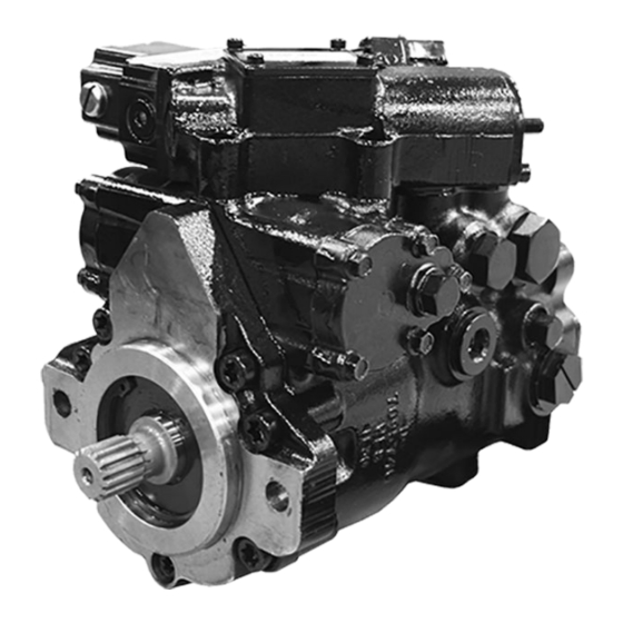
The legend above defines each symbol and explains its purpose. Design Danfoss Series 40 M46 closed-circuit axial-piston pumps convert input torque into hydraulic power. The input shaft transmits rotational force to the cylinder block. Bearings at the front and rear of the pump support the input shaft. -
Page 8: The System Circuit
Service Manual Series 40 M46 Variable Pumps Introduction Cross section view Gerotor Ball bearing Valve plate Piston Slipper Shaft Shaft Seal Journal Bearing Swashplate bearing pin Needle bearing Servo piston Cylinder block Swashplate Sleeve Bearing Manual displacement Control The system circuit The basic closed circuit Hydraulic lines connect the main ports of the pump to the main ports of the motor. -
Page 9: Pump Schematic
High pressure Case flow P106 608E Pump schematic Pump schematic B N A P100 587E Above schematic shows the function of a Series 40 M46 axial piston variable displacement pump. 11026743 | AX00000027en-US0202 | 9 © Danfoss | September 2017... -
Page 10: Fluid And Filter Maintenance
Service Manual Series 40 M46 Variable Pumps Fluid and filter maintenance Fluid and filter recommendations To ensure optimum life, perform regular maintenance of the fluid and filter. Contaminated fluid is the main cause of unit failure. Take care to maintain fluid cleanliness when servicing. -
Page 11: Initial Startup Procedures
Service Manual Series 40 M46 Variable Pumps Initial startup procedures General Follow this procedure when starting-up a new pump installation or when restarting an installation in which the pump was removed. Ensure pump is thoroughly tested on a test stand before installing. -
Page 12: Required Tools And Pressure Measurements
Service Manual Series 40 M46 Variable Pumps Required tools and pressure measurements Required tools The service procedures described in this manual can be performed using common mechanic’s hand tools. Special tools, if required, are shown. When testing system pressures, calibrate pressure gauges frequently to ensure accuracy. - Page 13 Service Manual Series 40 M46 Variable Pumps Required tools and pressure measurements Port locations P106 604E 11026743 | AX00000027en-US0202 | 13 © Danfoss | September 2017...
-
Page 14: Troubleshooting
Service Manual Series 40 M46 Variable Pumps Troubleshooting Overview This section provides general steps to follow if undesirable system conditions occur. Follow these steps until you solve the problem. Some of the items are system specific. For areas this manual covers, we reference the section. -
Page 15: System Will Not Operate In One Direction
Service Manual Series 40 M46 Variable Pumps Troubleshooting Item Description Action Oil filters Clogged oil filters may result in an insufficient Inspect the oil filters and verify that they are still supply of cool oil to the system. operable. Replace them if necessary. -
Page 16: Neutral Difficult Or Impossible To Find
Service Manual Series 40 M46 Variable Pumps Troubleshooting Item Description Action Charge pump The charge pump is damaged or has been installed Verify that the charge pump is in good working with the incorrect rotational orientation. order and that it is correctly installed. Repair or replace it as necessary. -
Page 17: Electrical Troubleshooting
Service Manual Series 40 M46 Variable Pumps Troubleshooting Item Description Action Servo pressure There is insufficient pressure differential across the Check servo pressures at port M4 and M5 to verify servo piston. sufficient pressure delta. Verify that the servo supply and drain paths are unobstructed and that each orifice is of the correct size and free of debris. -
Page 18: Adjustments
Performing installation, maintenance, and minor repairs according to the procedures in this manual will not affect your warranty. Major repairs requiring the removal of a unit’s front flange voids the warranty unless done by a Danfoss Global Service Partner. Pump adjustment This section offers instruction on adjustment of pump components. -
Page 19: Engaging The Bypass Function
Service Manual Series 40 M46 Variable Pumps Adjustments 7. Remove gages and replace plugs (M3, L1/L2). Using an 11/16 in. hex wrench, torque plug (M3) to 37 N•m [27 lbf•ft]. Using a 9/16 in. internal hex wrench, torque plug (L1/L2) to 115 N•m [85 lbf•ft]. -
Page 20: System Check/Relief (Scr) Valves
Service Manual Series 40 M46 Variable Pumps Adjustments Using the bypass function Bypass check valve 5/8 in P106 633E System check/relief (SCR) valves The SCR valve is a high pressure relief valve and a system check valve in combination. Whenever an SCR valve is replaced or opened, opperate the pump in its full range of functions to ensure proper machine operation. -
Page 21: Displacement Limiter Adjustment
Service Manual Series 40 M46 Variable Pumps Adjustments 6. Using a 1-1/4 in. hex wrench, install relief valve plug. Torque to 176 N•m [130 lbf•ft]. Installing the SCRs 1-1/4 in 176 Nm [130 ft•lb] 1103 1103 1-1/4 in 176 Nm [130 ft•lb]... -
Page 22: Swashplate Neutral Adjustment
Service Manual Series 40 M46 Variable Pumps Adjustments 5. After adjustment, verify proper maximum vehicle/machine speed. Readjust if necessary. Displacement limiter adjustment 9/16 in P106 626E Swashplate neutral adjustment With the pump properly plumbed, primed, and mounted on a vehicle or test stand, use this procedure to adjust mechanical neutral. -
Page 23: Manual Displacement Control Neutral-Return Bracket Adjustment
Service Manual Series 40 M46 Variable Pumps Adjustments 3. Run prime mover at normal operating speed. 4. Use a 1/4 hex wrench to hold adjusting screw (908) in place and a 9/16 hex wrench to loosen servo lock nut (115). -
Page 24: Electric Displacement Control/Hydraulic Displacement Control Neutral Adjustment
Service Manual Series 40 M46 Variable Pumps Adjustments opposite direction until the other servo pressure gage indicates an increase in pressure. Note position of bracket. Rotate neutral bracket half way between the two positions. 5. Holding the neutral adjustment bracket in place, use a 3/8 in. hex wrench to tighten screw (1210). -
Page 25: Hc Edc Control
Service Manual Series 40 M46 Variable Pumps Adjustments 6. Stop prime mover and remove previously installed gauges. Plug ports M4, M5. Torque to 37 N•m [27 lbf•ft] EDC / HDC control adjustment Adjustment screw 5/32 in Lock nut 9/16 in... - Page 26 Service Manual Series 40 M46 Variable Pumps Adjustments 3. Observe pressure gauges. If necessary, turn adjusting screw (D015) to reduce pressure differential. EDC adjustment is very sensitive. Be sure to hold the hex wrench steady while loosening the locknut. Total adjustment is less than 120 degrees.
- Page 27 Service Manual Series 40 M46 Variable Pumps Adjustments Neutral Adjustment (EDC) (bottom view) Solenoid shaft Control spool Adjusting screw (cam) Feedback pin Maximum adjustment less than 120° P106 046E Illustration shows how cam on adjusting pin rotates to adjust for neutral position after pump is re- installed.
-
Page 28: Minor Repair
1. Before replacing the pump on the machine, replace all filters and drain the hydraulic system. Fill the system with the correct, filtered, hydraulic fluid. 2. Flush the lines before replacing the hydraulic fluid. For repair part information, see Danfoss publication Series 40 M46 Variable Pump Parts Manual BLN-2-41701 for your model. Displacement limiter Removal Only remove displacement limiter (911) if replacement is necessary. -
Page 29: Pressure Filtration Adapter
Service Manual Series 40 M46 Variable Pumps Minor repair Inspection Inspect all parts for damage. Inspect the mating surfaces of the servo cover (902) and pump housing for scratches, grooves, and other damage. Inspect threads of screws and nuts for damage. Replace any damaged parts. -
Page 30: Charge Pump
Service Manual Series 40 M46 Variable Pumps Minor repair 3. Lubricate and install O-ring (810A) onto plug (810). Using an 11/16 in. hex wrench, install plug (810). Torque to 37 N•m [27 lbf•ft]. Pressure filtration adapter removal/installation 11/16 in 810A... - Page 31 Service Manual Series 40 M46 Variable Pumps Minor repair 5. Remove pin (604) and key (605). Charge pump removal/installation 1506 9/16 in 30Nm [20 ft•lb] 1502 9/16 in 43Nm [32 ft•lb] 1503 1505 1504 P106 636E Inspection Inspect the gerotor (603) and gerotor cover (155) for wear, scratches or pitting. If any component shows signs of wear, scratching, or pitting, relpace all components.
-
Page 32: Shaft Seal, Roller Bearing And Shaft Replacement
Service Manual Series 40 M46 Variable Pumps Minor repair 4. Using a 9/16 in. hex wrench, install screws (1502). Torque to 43 N•m [32 lb•ft]. 5. Lubricate and press seal (1504) onto auxiliary pad (1503). If a gear pump is a ttached to the auxiliary pad, install a new O-ring or gasket and gear pump 6. -
Page 33: Scr Valves
Service Manual Series 40 M46 Variable Pumps Minor repair Inspection Inspect the shaft and bearing for wear, scratching and pits. If wear, scratching or pitting is found, replace the shaft and bearing. Rotate bearing while feeling for roughness. Replace bearing if it doesn’t spin freely. -
Page 34: Charge Pressure Relief Valve
Service Manual Series 40 M46 Variable Pumps Minor repair 2. Lubricate and install new O-ring (106) onto plug (166). Using a 1-1/4 in. hex wrench install relief valve plug (166). Torque to 176 N•m [130 lbf•ft]. SCR valves 1-1/4 in 176 Nm [130 ft•lb]... -
Page 35: Bypass Valve
Service Manual Series 40 M46 Variable Pumps Minor repair 3. Operate pump at full range of controls to ensure proper machine operation. Charge pressure relief valve 1 in P106 638E Bypass valve Removal 1. Using a 5/8 in. hex wrench, remove bypass valve (1001). -
Page 36: Manual Displacement Control
Service Manual Series 40 M46 Variable Pumps Minor repair 3. Operate pump at full range of controls to ensure proper machine operation. Bypass valve 1001 5/8 in 20 Nm [15 ft•lb] 1002 1003 P106 653E Manual displacement control Removal 1. Using a 3/8 in. hex wrench, remove screw (1210). Remove manual control spool assembly from pump housing. -
Page 37: Electronic Displacement Control/Hydraulic Displacement Control
Service Manual Series 40 M46 Variable Pumps Minor repair Alignment slot Servo piston P107 958E 3. Install neutral return spring (1214), neutral return bracket (1216), handle (1215), and washer (1235) onto spool (1207). 4. Using a 1/2 in. hex wrench, install lock nut (1213). Torque to 15 N•m [11 lbf•ft]. - Page 38 Service Manual Series 40 M46 Variable Pumps Minor repair 1. Using a 3/16 in. internal hex wrench, remove screws (1203 and 1204) or (1224). If you have a three position controll, remove screws (1226) using a 4 mm internal hex wrench.
-
Page 39: Mdc Orifice Repair
Service Manual Series 40 M46 Variable Pumps Minor repair 2. If you have a three position control, use a 4 mm internal hex wrench to install screws (1226). Torque screws to 14 N•m [10 lbf•ft]. Install three posion control housing (1223). Using a 3/16 in. internal hex wrench, install screws (1203 and 1204) or (1224). -
Page 40: Edc/Hdc Orifice Repair
Service Manual Series 40 M46 Variable Pumps Minor repair MDC orifice repair 1401 1/8 in 1219 3/16 in P106 654E EDC/HDC orifice repair Removal 1. Remove servo covers. See Displacement limiter on page 28, for servo cover removal and installation instructions. -
Page 41: Hc Edc Control Repair
Service Manual Series 40 M46 Variable Pumps Minor repair 2. Install servo covers. See Displacement limiter on page 28, for servo cover removal and installation instructions. EDC/HDC orifice repair 3/8 in 2161 1403 1404 3/8 in 9/16 in P106 655E HC EDC Control Repair 1. - Page 42 Service Manual Series 40 M46 Variable Pumps Minor repair 5. If you removed screen (D084), install a new one. Install with the mesh facing outward (see drawing). Proper screen orientation P106 519E 6. Install the control module and six cap screws (D250).
- Page 43 Service Manual Series 40 M46 Variable Pumps Minor repair 7. Using a 5 mm internal hex wrench, torque the cap screws (D250) to 13.5 N•m [10 lbf•ft]. HC ECD Control D250 (6X) 5 mm D084 D150 D200 D300 (2X) P108776...
-
Page 44: Torque Chart
Service Manual Series 40 M46 Variable Pumps Torque chart Fastener size and torque chart Item Fastener Wrench size Torque Servo piston cover screws 3/8 hex 15 N•m [11 lbf•ft] Servo piston cover screws 3/8 hex 15 N•m [11 lbf•ft] Front cover screw T50 Torx 58 N•m [43 lbf•ft]... - Page 45 Service Manual Series 40 M46 Variable Pumps Torque chart Hardware locations 1210 1213 (2places) (6 places) Side (2 places) Front 1506 Rear (3 places) (3 places) (2 places) 1102 1001 (2 places) (5 places) P106 604E (2 places) (5 places)
- Page 46 Service Manual Series 40 M46 Variable Pumps 11026743 | AX00000027en-US0202 46 | © Danfoss | September 2017...
- Page 47 Service Manual Series 40 M46 Variable Pumps 11026743 | AX00000027en-US0202 | 47 © Danfoss | September 2017...
- Page 48 Phone: +86 21 3418 5200 Danfoss can accept no responsibility for possible errors in catalogues, brochures and other printed material. Danfoss reserves the right to alter its products without notice. This also applies to products already on order provided that such alterations can be made without changes being necessary in specifications already agreed.
Need help?
Do you have a question about the Series 40 M46 and is the answer not in the manual?
Questions and answers