
Related Manuals for Danfoss 45 K2 Series


Summary of Contents for Danfoss 45 K2 Series
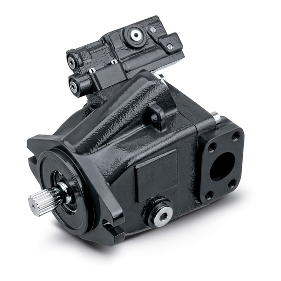
- Page 1 Repair Instructions Axial Piston Open Circuit Pumps Series 45 K2 powersolutions.danfoss.com...
- Page 2 Repair Instructions Series 45 Frame K2 Axial Piston Pumps Revision history Table of revisions Date Changed April 2017 First edition 0101 © Danfoss | April 2017 AX00000305en-US0101...
-
Page 3: Table Of Contents
Repair Instructions Series 45 Frame K2 Axial Piston Pumps Contents Introduction Overview......................................4 General instructions..................................4 Safety Precautions....................................5 Symbols used in Danfoss literature............................6 Disassembly Auxiliary pad.......................................7 Remove control....................................8 Displacement limiter..................................8 Servo piston......................................9 Disassembly....................................9 Endcap and valve plate.................................. 9 Cylinder kit......................................10 Input shaft and swashplate................................ -
Page 4: Overview
Only Danfoss Authorized Service Centers (ASCs) are authorized to perform major repairs. Danfoss ASCs are trained by the factory to perform major repairs and their facilities are certified on a regular basis. -
Page 5: Safety Precautions
Never use your hand or any other body part to check for leaks in a pressurized line. Seek medical attention immediately if you are cut by hydraulic fluid. Personal safety Warning Protect yourself from injury. Use proper safety equipment, including safety glasses, at all times. © Danfoss | April 2017 AX00000305en-US0101 | 5... -
Page 6: Symbols Used In Danfoss Literature
Repair Instructions Series 45 Frame K2 Axial Piston Pumps Introduction Symbols used in Danfoss literature WARNING may result in injury Tip, helpful suggestion CAUTION may result in damage to product or Lubricate with hydraulic fluid property Reusable part Apply grease / petroleum jelly... -
Page 7: Disassembly
5. Remove the coupling (J140). J130 J130 J110 J110 J120 J120 J100 J100 J085 J085 J090 J090 J095 J095 J140 J140 P109053 Item Wrench size J130 9/16 inch J110 8 mm internal hex © Danfoss | April 2017 AX00000305en-US0101 | 7... -
Page 8: Remove Control
The L030 adjustment seal/nut serves as a locking seal/nut, preventing the L040 screw from backing out. 2. Remove the adjustment screw (L040). Remove plug (L010) with a 1 1/4 in. wrench. Discard the O-ring (L010A). © Danfoss | April 2017 AX00000305en-US0101... -
Page 9: Servo Piston
1. Remove plug (L010) with a 1 1/4 in. wrench. Discard the O-ring (L010A). 2. Remove servo piston (P025) from housing. P109065 Endcap and valve plate 1. Remove the 4 endcap screws (J030) using an 8 mm internal hex wrench. © Danfoss | April 2017 AX00000305en-US0101 | 9... -
Page 10: Cylinder Kit
3. Slide the rear tapered roller bearing cone (B020) from the bottom end of the shaft. The bearing cup (B010) may remain within the endcap. Cylinder kit 1. Position pump on its side. 10 | © Danfoss | April 2017 AX00000305en-US0101... -
Page 11: Input Shaft And Swashplate
4. Carefully pry to remove the journal bearings (B030) and retaining pins (B071) from the pump housing. Record the location and orientation of the journal bearings if they are to be reused. If necessary, remove the front bearing cup (B060) from the pump housing. © Danfoss | April 2017 AX00000305en-US0101 | 11... -
Page 12: Shaft Seal
Repair Instructions Series 45 Frame K2 Axial Piston Pumps Disassembly J010 B040 B025 B071 B030 B050 B060 P109042 Shaft seal 12 | © Danfoss | April 2017 AX00000305en-US0101... -
Page 13: Control
Remove the adjusting screw (C138) and O-ring (C138A). Discard the O-ring. Remove the springs (C134, C135) along with the spring guide (C133). Disassemble the PC control C103 dC103A C132 C102 C133 C135 C134 dC138A C138 E101 193 © Danfoss | April 2017 AX00000305en-US0101 | 13... - Page 14 7. Remove plug (C104), and spool (C112). Note the orientation of the spool for reassembly. 8. Remove four screws (C151). Remove the manifold (C152) and discard the two interface O-rings (C154). 9. For electric proportional controls only: Remove the electric control manifold drain orifice (C149). 14 | © Danfoss | April 2017 AX00000305en-US0101...
- Page 15 The valve is only available as a complete assembly (QC150). If it is necessary to remove the orifice (H020), use a 3 mm internal hex wrench. Torque it to 2.7 Nm [24 in-lb] when it is installed in the manifold. © Danfoss | April 2017 AX00000305en-US0101 | 15...
- Page 16 5. Remove spring (C124) and spring guide (C123). 6. Remove the pressure limiter adjuster (C128). 7. Remove spring (C125) and spool (C122). 8. Remove plug (C107) and plug (C129). 9. Remove gain orifice (H030). 16 | © Danfoss | April 2017 AX00000305en-US0101...
-
Page 17: Cylinder Block Kit Disassembly
2. Remove the ball guide (K047). 3. Remove the 3 pins (K046). Most repairs do not require block spring removal. Perform this procedure only if you suspect problems with the block spring. © Danfoss | April 2017 AX00000305en-US0101 | 17... - Page 18 Ensure the spring is secure before attempting to remove the spiral retaining ring. Release the pressure slowly after the retaining ring is removed. 18 | © Danfoss | April 2017 AX00000305en-US0101...
-
Page 19: Inspection
P101 471 Block spring, and washers If cylinder kit was fully dissembled, visual inspection of the cylinder block, spring, and washers should indicate minimal wear. Replace if cracks or other damage is present. © Danfoss | April 2017 AX00000305en-US0101 | 19... -
Page 20: Cylinder Block
Check the spool’s outside diameter for scratches and / or burrs. Clean and coat all spools, bores, and seals with a light coating of hydraulic oil. 20 | © Danfoss | April 2017 AX00000305en-US0101... - Page 21 E101 181 Electric control C103 C125 C104 C132 C300 C112 C155 C102 C150 C149 C154 C152 G030 G020 C200 C151 C133 C113 C135 C115 C153 C114 C134 C138A C118 P108 668E C138 © Danfoss | April 2017 AX00000305en-US0101 | 21...
-
Page 22: Fan Drive Control
Replace the coil if necessary. 9. Check the control o-rings for damage, or cracks and replace if necessary. 10. Clean and lubricate all spools, bores, and seals with a light coating of hydraulic oil. 22 | © Danfoss | April 2017 AX00000305en-US0101... -
Page 23: Shaft
Inspect the journal bearings for damage or excessive wear. Replace journal bearings if scratched, warped, or excessively worn. The polymer wear layer must be smooth and intact. Inspect journal bearings B030 P101 363 © Danfoss | April 2017 AX00000305en-US0101 | 23... -
Page 24: Valve Plate
The tapered roller bearing kits consist of a cup and cone. Both the cup and cone should be free of excessive wear and contamination. Rotate the bearings to check for smoothness. If a contaminated bearing is suspected, clean with a solvent and lubricate with hydraulic fluid. If the problem is not 24 | © Danfoss | April 2017 AX00000305en-US0101... -
Page 25: Servo Piston
Replace if any wear is noticeable. P025 P109045 Endcap 1. Inspect the endcap. 2. Check and record the orientation of the timing pin (J050). 3. Carefully check the bearing cup for wear. J050 J051 P109046 Swashplate © Danfoss | April 2017 AX00000305en-US0101 | 25... -
Page 26: Displacement Limiter
(L030) for irregular wear. Replace if necessary. Replace the O-ring (L010A). Displacement Limiter Auxiliary Pad Inspect all machined surfaces on the auxiliary pad. If any damage or wear is found, replace the auxiliary pad. P109059 26 | © Danfoss | April 2017 AX00000305en-US0101... -
Page 27: Reassembly
(B040) with hydraulic fluid. Tilt the bias spring inward towards the center of the pump housing. To insert the swashplate, tilt the servo arm downward and into the © Danfoss | April 2017 AX00000305en-US0101 | 27... -
Page 28: Input Shaft
Be sure to install the slipper retainer so it mates correctly with the ball guide (concave side of the slipper retainer against the convex side of the ball guide). Assemble cylinder kit K050 K049 K047 K048 (L Frame only) K046 P010 K041 K042 K043 K044 K045 P101 356 28 | © Danfoss | April 2017 AX00000305en-US0101... -
Page 29: Cylinder Kit Installation
Install and torque endcap screws at 47.5 to 61 N•m [35 to 45 lbf•ft], using the criss cross pattern, and retorque the first screw to ensure proper torque retention. Install endcap components B070 B020 B010 J050 J051 J020 P109039 © Danfoss | April 2017 AX00000305en-US0101 | 29... -
Page 30: Shaft Seal
3. Press the seal into the housing until it is deep enough to allow the retaining ring to be installed. Press evenly to avoid binding and damaging the seal. 4. Install snap ring (K010). K010 K020 P109058 30 | © Danfoss | April 2017 AX00000305en-US0101... -
Page 31: Pc Control
3. Install and tighten set screw (C102) at 7.5 to 10.8 N•m [5.5 to 8.0 lbf•ft]. Also, install the plugs (C105, C106) with new O-rings. Torque the plugs at 10.8 to 13.5 N•m [8 to 10 lbf•ft]. PC and LS spools need to be adjusted to proper setting according to tag nomenclature. © Danfoss | April 2017 AX00000305en-US0101 | 31... - Page 32 Series 45 Frame K2 Axial Piston Pumps Reassembly Assemble PC/LS control tC103 C104 dC103A C104A RC132 C112 C105 dC106A C105A tC106 C113 tC102 C115 C114 C133 C117 C135 C116 C117 C134 C118 dC136 C138 E101 189 32 | © Danfoss | April 2017 AX00000305en-US0101...
-
Page 33: Fan Drive Control
C107 Plug 7/16" 3/16" internal hex 13.7 N•m [9.9 lbf•ft] C128C Nut 9/16" 17 mm exter hex 23.7 N•m [17.5 lbf•ft] C120 Solenoid cartridge 17 mm exter hex 25.75 N•m [19 lbf•ft] © Danfoss | April 2017 AX00000305en-US0101 | 33... -
Page 34: Install The Control
Install auxiliary mounting pad 1. Install the adapter (J080) with new O-rings (J090, J095). Tighten the screws (J100) at 47.5 to 61 N•m [35 to 45 lbf•ft]. 2. Install the coupling (J140) onto the shaft. 34 | © Danfoss | April 2017 AX00000305en-US0101... -
Page 35: Install Servo Piston
A pad, install the J130 screws at 37 to 50 N•m [27 to 37 lbf•ft]. J130 J130 J110 J110 J120 J120 J100 J100 J085 J085 J090 J090 J095 J095 J140 J140 P109053 Install servo piston 1. Lubricate servo piston and install in the housing. © Danfoss | April 2017 AX00000305en-US0101 | 35... -
Page 36: Install Displacement Limiter
4. Using a 19mm exter hex wrench torque the adjustment seal/nut (L030) to 54 N•m [40 lbf•ft]. Refer to Frame K2 Service Manual AX00000301 for instructions on adjusting displacement limiter. Displacement Limiter 36 | © Danfoss | April 2017 AX00000305en-US0101... - Page 37 Repair Instructions Series 45 Frame K2 Axial Piston Pumps © Danfoss | April 2017 AX00000305en-US0101 | 37...
- Page 38 Repair Instructions Series 45 Frame K2 Axial Piston Pumps 38 | © Danfoss | April 2017 AX00000305en-US0101...
- Page 39 Repair Instructions Series 45 Frame K2 Axial Piston Pumps © Danfoss | April 2017 AX00000305en-US0101 | 39...
- Page 40 Phone: +86 21 3418 5200 Danfoss can accept no responsibility for possible errors in catalogues, brochures and other printed material. Danfoss reserves the right to alter its products without notice. This also applies to products already on order provided that such alterations can be made without changes being necessary in specifications already agreed.
Need help?
Do you have a question about the 45 K2 Series and is the answer not in the manual?
Questions and answers