
Related Manuals for Danfoss Digital Displacement DDP096


Summary of Contents for Danfoss Digital Displacement DDP096
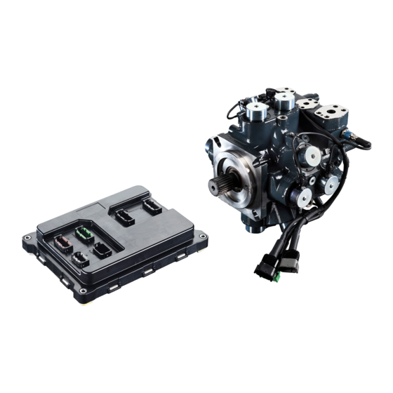
- Page 1 Technical Information Digital Displacement DDP096 pump and DPC12 controller www.danfoss.com...
- Page 2 Revised to reflect updated specifications 0202 June 2021 Added new Gen 1 content; recreated document structure 0201 December 2019 Revised to reflect 420 bar limit and updated software features 0102 October 2019 First edition: 280 bar, industrial 0101 © Danfoss | October 2023 BC306384089197en-000202...
-
Page 3: Table Of Contents
Overview......................................24 ® PLUS+1 CAN/USB gateway..............................24 Configuration and tuning..............................24 Commissioning mode................................25 Diagnostics and errors................................25 Model code DDP model code.................................... 26 DDP part options....................................27 Mechanical installation Pump transport and handling..............................29 Storage.......................................30 Installation requirements................................30 © Danfoss | October 2023 BC306384089197en-000202 | 3... - Page 4 Commissioning and troubleshooting Basic commissioning procedure.............................. 58 Commissioning and troubleshooting with PLUS+1 Service Tool................58 Initial procedure..................................58 Commissioning DDP valves and hydraulic installation....................58 Further system commissioning and validation......................59 Symptoms and diagnosis................................60 Serviceability....................................60 © Danfoss | October 2023 BC306384089197en-000202...
-
Page 5: General Information
To pump each piston, the controller closes the solenoid valve when the piston is at bottom dead center. The inlet check valve closes and the piston forces the fluid through the outlet check valve. When the © Danfoss | October 2023 BC306384089197en-000202 | 5... -
Page 6: Multi-Outlet Pump
However, the multi-outlet DDP leverages the four pumplets to offer multiple outputs from a single pump with independent flows, pressures, and control modes. © Danfoss | October 2023 BC306384089197en-000202... - Page 7 P1, P2, and P4 represent the outlet ports of the multi-outlet DDP096 endcap. (P2+P4) means that the P2 and P4 ports must be connected with a ganging manifold. Refer to Pump dimensions for more information on ports. © Danfoss | October 2023 BC306384089197en-000202 | 7...
-
Page 8: Features And Benefits
Always relieve pressure in the system before removing hoses, fittings, gauges, or other components. Never use hands or any other body parts to check for leaks in a pressurized component; seek medical attention immediately if you are cut by hydraulic fluid. © Danfoss | October 2023 BC306384089197en-000202... -
Page 9: Oem Responsibility
General information OEM responsibility The OEM of a machine or vehicle in which Danfoss products are installed has the full responsibility for all consequences that might occur. Danfoss has no responsibility for any consequences, direct or indirect, caused by failures or malfunctions. -
Page 10: Improper Use
The system operates with high pressure fluid. Assembly and disassembly of the pump for maintenance purposes is only to be carried out by Danfoss or a qualified service technician authorized by Danfoss. Installation of the pump and electrical equipment must be carried out by suitably qualified personnel with experience and knowledge of working with hydraulic and electrical systems. -
Page 11: Technical Specifications
Maximum intermittent 100 [212] Cleanliness per ISO4406:1999 Recommended 17/15/12 Minimum 18/16/13 Special procedure is required for cold start. Contact your Danfoss representative for details. DDP mechanical specifications Description Value Notes Front mounting flange SAE C 4-bolt Flange 127-4 adhering to ISO 3019-1 (SAE... - Page 12 7 M14 x 1.5 steel plugs Per ISO 6149-1 Handling brackets 3 (2 at the rear and 1 on pumplet 1) Only intended for lifting pump and Danfoss supplied sensors/wiring Pump wiring harness connectors DTM04-12PC (green) – C3 C3 is for the sensor harness DTM04-12PA (grey) –...
-
Page 13: Dpc12 Controller Specifications
Pressure sensors for DPC12 While the DDP096 pump is already equipped with pressure sensor(s), additional pressure sensor(s) may be required for load sensing operation in addition to software configuration. © Danfoss | October 2023 BC306384089197en-000202 | 13... -
Page 14: Non-Volatile Memory Write/Erase Ratings
Climate environmental standards Description Applicable standard Storage operating IEC 60068-2-1, test Ab IEC 60068-2-2 test Bb Operating temperature IEC 60068-2-1, test Ab IEC 60068-2-2, test Bd Degree of protection (IP) IEC 60529 14 | © Danfoss | October 2023 BC306384089197en-000202... -
Page 15: Led Messages
Auto electrical transients Road vehicles — Electrical disturbances from conduction ISO 7637-2 and coupling ISO 7637-3 For more information about criteria and standards please contact your Danfoss representative. LED messages LED characteristics meaning Characteristic Indication Magenta; blink rate 1.5 Hz Device is in BOOT-LOADER mode Blue;... -
Page 16: Ddp Characteristics
As a result, the idle losses of the DDP096 are independent from the outlet pressure. While in idling mode, the discharge flow of the pump is exactly 0 L/min. Theory of operation on page 5 for more information. 16 | © Danfoss | October 2023 BC306384089197en-000202... -
Page 17: Pump Discharged Flow And Shrinkage
“Flow rate / Shaft Speed” (i.e. pump displacement) presented in the graph below. For example, at 400 bar and 2500 rpm the DDP096 pump displaces a maximum of 88.5 cc/rev, equivalent to 177 L/min. © Danfoss | October 2023 BC306384089197en-000202 | 17... -
Page 18: Input Torque
Due to internal compressed energy recovery, the torque and input power follow the same rule as the pump discharge flow; the input torque and power increases less with pressure than would be expected from the theoretical value. 18 | © Danfoss | October 2023 BC306384089197en-000202... -
Page 19: Electronic Control Losses
In some systems, DDP can generate system level noise. It is important to mitigate such vibrations by adequately isolating the pump from the rest of the system. Refer to the Understanding and minimizing system noise on page 31 for more information on countermeasures. © Danfoss | October 2023 BC306384089197en-000202 | 19... -
Page 20: Control Operation
The DPC12 offers different modes for controlling the pump and to aid in system startup. Parameters are used to set the behavior of the DPC12 and are selected through use of the Danfoss PLUS+1 ® Service Tool and diagnostic file (P1D). -
Page 21: Other Features
Not all limits can be applied together or with the principle control modes. The specific valid combinations depend on the software version. Refer to the Software Manual for details or contact your Danfoss representative for available combinations. Other features... -
Page 22: Control Diagrams
Technical Information Digital Displacement® DDP096 pump and DPC12 controller Control operation Control diagrams Service control algorithm diagram 22 | © Danfoss | October 2023 BC306384089197en-000202... - Page 23 A load-sense pressure signal is required from a pressure sensor in the load-sense resolving network of the service if Load-Sense Mode is used. The proportional gains and integration time are tuned via non-volatile parameters. Contact your Danfoss representative for details on tuning these parameters.
-
Page 24: Example Use Cases
® ® Communication occurs over the CAN bus and a CAN gateway such as the Danfoss CG150 is required. The diagnostic file allows parameter changes which select the control mode, limits, tuning gains, and other features. These parameters are saved in non-volatile memory. There are also pages to interact with Commissioning Mode and to see past and active Errors. -
Page 25: Commissioning Mode
After the action type is chosen, action type specific interfaces will be available on screen. To exit Commissioning mode, press the Exit Commissioning Mode button, then follow the prompts. For more information on Commissioning Mode parameters and interaction, contact your Danfoss representative. -
Page 26: Model Code
Tandem pump endcap Tandem pump sensors and harness Tandem pump common parts Accessory block Paint and nametag Special hardware or features Electronic hardware Electronic hardware nametag Software build Software version Software parameter set 26 | © Danfoss | October 2023 BC306384089197en-000202... -
Page 27: Ddp Part Options
Inlet port S: DN 51 ISO 6162-1; M12 x 1.75 Outlet port P1: DN 19 ISO 6162-2; M10 x 1.5 Outlet port P2: DN 13 ISO 6162-2; M8 x 1.25 Outlet port P4: DN 13 ISO 6162-2; M8 x 1.25 © Danfoss | October 2023 BC306384089197en-000202 | 27... - Page 28 For a 3-service pump (speed/temperature sensor W; pressure sensors M1, M2 & M4) K; Common parts R; Accessory block None S; Paint and pump nametag Black paint; Danfoss standard tag T; Special hardware None U; Electronic hardware DPC12 pump controller V;...
-
Page 29: Mechanical Installation
Do not directly or indirectly strike the coupling or driveshaft of the pump as this may cause internal damage. Do not drop the pump. If dropped, do not use the pump and contact your Danfoss representative. There are three handling brackets on DDP096 pumps. One bracket is on one side of the housing (pumplet 1) and the two other brackets are opposite of each other on the endcap at the rear of the pump. -
Page 30: Storage
The installation locations and position of the pump must be as described in this document. Adhere to all limits specified in the DDP096 pump specifications section regarding pressure, temperature, viscosity and cleanliness of the hydraulic fluid. Other configurations are possible; please contact your Danfoss representative for direction. -
Page 31: Understanding And Minimizing System Noise
Contact your Danfoss representative for more support. Special control methods are recommended for systems with multiple DDP units connected in parallel to the same hydraulic load. -
Page 32: Removing Air Through The Ddp Outlet Port
Ensure that the shaft is not spinning while the discharge port is not connected to the final hydraulic circuit. If the shaft is spinning, the DDP could pump and the outlet line could over-pressurize. Over-pressurizing the outlet line creates a risk of injury and damage. 32 | © Danfoss | October 2023 BC306384089197en-000202... -
Page 33: Removing Air By Submersion
Suction strainers can have similar effects. If you plan to use a suction strainer, discuss it with your Danfoss representative. Return line filtration is the preferred method for open circuit systems. Consider these factors when selecting a system filter: •... - Page 34 Operating the DPC12 over the maximum temperature value can cause the controller to overheat and disable pumping. Refer to General ratings on page 14 for acceptable ambient temperatures. Fasteners for DPC12 controller only Recommended outer diameter (OD) 6 mm [1/4 inch] 34 | © Danfoss | October 2023 BC306384089197en-000202...
-
Page 35: Pump Dimensions
Coil harness “A” Coil C3 Coil 3 from bank C Coil harness “B” Coil C4 Coil 4 from bank C Coil harness “B” Common dimensions are made on drawings from the single-outlet pump. © Danfoss | October 2023 BC306384089197en-000202 | 35... -
Page 36: Shaft End View Dimensions
Technical Information Digital Displacement® DDP096 pump and DPC12 controller Mechanical installation Shaft end view dimensions Dimensions in mm* Unique to single-outlet pumps 36 | © Danfoss | October 2023 BC306384089197en-000202... -
Page 37: Flange Dimensions
Technical Information Digital Displacement® DDP096 pump and DPC12 controller Mechanical installation Flange dimensions Dimensions in mm © Danfoss | October 2023 BC306384089197en-000202 | 37... -
Page 38: Side View Dimensions
Technical Information Digital Displacement® DDP096 pump and DPC12 controller Mechanical installation Side view dimensions Shaft oriented right; dimensions in mm 38 | © Danfoss | October 2023 BC306384089197en-000202... - Page 39 Technical Information Digital Displacement® DDP096 pump and DPC12 controller Mechanical installation Shaft oriented right; dimensions in mm © Danfoss | October 2023 BC306384089197en-000202 | 39...
- Page 40 Technical Information Digital Displacement® DDP096 pump and DPC12 controller Mechanical installation Shaft oriented left; dimensions in mm Unique to single-outlet pumps 40 | © Danfoss | October 2023 BC306384089197en-000202...
-
Page 41: Top View Dimensions
Technical Information Digital Displacement® DDP096 pump and DPC12 controller Mechanical installation Top view dimensions Dimensions in mm Unique to single-outlet pumps © Danfoss | October 2023 BC306384089197en-000202 | 41... -
Page 42: Rear View Dimensions
Technical Information Digital Displacement® DDP096 pump and DPC12 controller Mechanical installation Rear view dimensions Dimensions in mm Unique to single-outlet pumps 42 | © Danfoss | October 2023 BC306384089197en-000202... -
Page 43: Single-Outlet Pump Dimensions
Handling brackets: 14.2 mm [0.56 in] hole diameter Shaft spline (see Shaft spline data below) Speed/temperature sensor; DEUTSCH DTM04-4 connector Pressure sensor M; DEUTSCH DT04-3 connector Approximate center of gravity for single-outlet pump © Danfoss | October 2023 BC306384089197en-000202 | 43... - Page 44 Number of teeth 16/32 Pitch fraction 30° Pressure angle 36.513 mm [1.438 in] Pitch diameter 37.59 ± 0.08 [1.48 in] Major diameter Fillet root side Type of fit ANSI B92.1b-1996 class 6e Specification 44 | © Danfoss | October 2023 BC306384089197en-000202...
-
Page 45: Multi-Outlet Pump Dimensions
Technical Information Digital Displacement® DDP096 pump and DPC12 controller Mechanical installation Multi-outlet pump dimensions For other dimensions, see Common dimensions on page 35 and Single-outlet pump dimensions on page Dimensions in mm © Danfoss | October 2023 BC306384089197en-000202 | 45... -
Page 46: Multi-Outlet Pump Side View Dimensions
Technical Information Digital Displacement® DDP096 pump and DPC12 controller Mechanical installation Multi-outlet pump side view dimensions Shaft oriented right; dimensions in mm 46 | © Danfoss | October 2023 BC306384089197en-000202... - Page 47 Technical Information Digital Displacement® DDP096 pump and DPC12 controller Mechanical installation Shaft oriented left; dimensions in mm © Danfoss | October 2023 BC306384089197en-000202 | 47...
-
Page 48: Multi-Outlet Pump Rear View Dimensions
DN 19 (Ø19) ISO 6162-2 M10 x 1.5; 19 mm full min thread Paint free Pressure port 2: Split flange boss DN 13 (Ø12.5) ISO 6162-2 M8 x 1.25; 16 mm full min thread Paint free 48 | © Danfoss | October 2023 BC306384089197en-000202... - Page 49 Paint free Pressure sensor M1; DEUTSCH DT04-3 connector Pressure sensor M2; DEUTSCH DT04-3 connector Pressure sensor M4; DEUTSCH DT04-3 connector Please contact your Danfoss representative for specific dimension drawings or to discuss ganging manifold designs. © Danfoss | October 2023...
-
Page 50: Controller Dimensions
Minimum clearance to install the mating receptacles Power connection System connection Sensor connection Coil harness “A” connection Coil harness “B” connection Communication connection Receptacles for the controller wiring harness. For more information, see Connectors on page 55. 50 | © Danfoss | October 2023 BC306384089197en-000202... -
Page 51: Electrical Installation
The DDP096 comes with a wiring harness that must be connected to the DPC12 via the pump-to- controller wiring harness. The DPC12 must also be connected to a power supply and, if applicable, a CAN bus. For more information about the DPC12 connections, see Connectors on page 55. © Danfoss | October 2023 BC306384089197en-000202 | 51... -
Page 52: Machine Wiring Guidelines
To reduce resistive power losses, the power supply cable to the DPC12 controller should use the maximum wire gauge the connector can accept (2 mm or 14 AWG) and be as short as possible; the maximum length should not be longer than 10 meters, contact your Danfoss representative otherwise Caution Avoid accidentally connecting incorrect pins to supply power. -
Page 53: Machine Welding Guidelines
The DPC12 baseplate must be earthed through its mounting fasteners. All DPC12 ground pins are internally connected and should use the same wire gauge. © Danfoss | October 2023 BC306384089197en-000202 | 53... -
Page 54: Hot Plugging
Technical Information Digital Displacement® DDP096 pump and DPC12 controller Electrical installation Hot plugging Shut off machine power when connecting the DPC12 to mating connectors. 54 | © Danfoss | October 2023 BC306384089197en-000202... -
Page 55: Connectors
Gold-Tin reactions which can compromise the connection. Connector plug Type 12 pin DTM 8 pin DTM 8 pin DT Gray A-key DTM06-12SA DTM06-08SA DT06-08SA Black B-key DTM06-12SB Green C-key DTM06-12SC Brown D-key DTM06-12SD © Danfoss | October 2023 BC306384089197en-000202 | 55... -
Page 56: Pump Connectors
3.68mm [0.145 in] Sealing plugs 0413-204-2005 0413-204-2005 Sealing pin: 114017-zz Locking sealing pin: 0413-217-1605 Contact Danfoss for further information on compatible DEUTSCH products and tools. Pump connectors Pump connector descriptions Label Connector Description Mating receptacle (for pump-to- controller harness) Sensor connector... -
Page 57: Controller Connectors
DEUTSCH DTM04-12PC (green) DEUTSCH DTM06-12SC (green) Coil harness “A” DEUTSCH DTM04-12PA (gray) DEUTSCH DTM06-12SA (gray) connection Coil harness “B” DEUTSCH DTM04-12PB (black) DEUTSCH DTM06-12SB (black) connection Comm connection DEUTSCH DTM04-08PA (gray) DEUTSCH DTM06-08SA (gray) © Danfoss | October 2023 BC306384089197en-000202 | 57... -
Page 58: Commissioning And Troubleshooting
Perform the commissioning process at low pressure to minimize risk of oil spray. Commissioning DDP valves and hydraulic installation Make sure the DPC12 is in commissioning mode before starting the prime mover. 58 | © Danfoss | October 2023 BC306384089197en-000202... -
Page 59: Further System Commissioning And Validation
3. Compare expected discharged flow with actuator speed, or flow measurement. If issues persist, contact Danfoss for assistance. Do not attempt to disassemble the pump. The pump is not field serviceable and special tools and procedures are required for assembly and disassembly. -
Page 60: Symptoms And Diagnosis
(unstable or oscillating) Sensor disconnected or damaged Wiring harness damaged Pump not bled Gain settings need to be adjusted in the pressure control loop – contact Danfoss Non-continuous output flow Pressure limit set in controller being reached (pump stops and starts randomly) - Page 61 Phone: +86 21 2080 6201 Danfoss can accept no responsibility for possible errors in catalogues, brochures and other printed material. Danfoss reserves the right to alter its products without notice. This also applies to products already on order provided that such alterations can be made without subsequent changes being necessary in specifications already agreed.
Need help?
Do you have a question about the Digital Displacement DDP096 and is the answer not in the manual?
Questions and answers