
Related Manuals for Danfoss 45 Frame K2 Series


Summary of Contents for Danfoss 45 Frame K2 Series
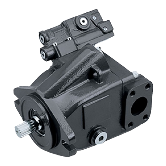
- Page 1 Service Manual Open Circuit Axial Piston Pumps Series 45 Frame K2 powersolutions.danfoss.com...
- Page 2 Service Manual Series 45 Frame K2 Open Circuit Axial Piston Pumps Revision history Table of revisions Date Changed April 2017 First edition 0101 © Danfoss | April 2017 AX00000301en-US0101...
-
Page 3: Table Of Contents
Using this manual.....................................5 Safety precautions....................................5 Unintended machine movement............................5 Flammable cleaning solvents..............................5 Fluid under pressure.................................. 5 Personal safety..................................... 5 Symbols used in Danfoss literature............................6 General description..................................6 Technical specifications General specifications..................................8 Type of mounting..................................8 Auxiliary mounting pad options............................8 Control options....................................8 Port options....................................8... - Page 4 Auxiliary pads....................................28 Disassembly....................................28 Inspection....................................29 Assembly......................................29 LS and PC Controls..................................29 Electric Controls....................................33 Fan Drive Control................................... 34 Servo Control Orifice..................................36 Servo Control Orifice Disassembly............................. 36 Servo Control Orifice Reassembly............................37 Plug and fitting sizes and torques............................37 © Danfoss | April 2017 AX00000301en-US0101...
-
Page 5: Using This Manual
A worldwide network of Danfoss Authorized Service Centers (ASCs) is available should major repairs be needed. Contact any Danfoss ASC for details. A list of all ASCs can be found in bulletin BLN-2-40527, or in brochure SAW (Ident. No. 698266), or you can locate your nearest ASC using the distributor locator at http://www.powersolutions.danfoss.com... -
Page 6: Symbols Used In Danfoss Literature
The legend above defines each symbol and explains its purpose. General description Danfoss Series 45 K2 frame open circuit piston pumps convert input torque into hydraulic power. Rotational force is transmitted through the input shaft to the cylinder block. The input shaft is supported by tapered roller bearings at the front and rear of the pump and is splined into the cylinder block . - Page 7 LS adjustment PC spool PC adjustment Servo piston Swashplate Cylinder block Bias spring Slipper Valve plate Slipper retainer Piston Tapered roller bearing Endcap Input shaft (axial ported) Shaft seal Block spring P109038 © Danfoss | April 2017 AX00000301en-US0101 | 7...
-
Page 8: Technical Specifications
0.716 [438] (theoretical) at 49° C [120°F] 1000 psi] Mass moment of inertia of internal rotating kg•m [slug•ft 0.00184 [0.00135] 0.00203 [0.00150] components Weight Axial ports kg [lb] 16 [35] Radial ports 17 [37] © Danfoss | April 2017 AX00000301en-US0101... -
Page 9: Hydraulic Parameters
(cold start) 1000 [4700] Filtration Required cleanliness level: ISO 4406 Class 18/13 or better. Refer to Danfoss publications Fluids and Filtration BLN-9887 or 520L0463 and Design Guidelines for Selecting and Maintaining the Required Hydraulic Fluid Cleanliness 520L0465. See Fluid and filter maintenance for recommended fluid and filter change intervals. -
Page 10: Features
The drive coupling is lubricated by oil from the main pump case. For details refer to Series 45 Axial Piston Open Circuit Pumps Technical Information TIM 520L0519. 10 | © Danfoss | April 2017 AX00000301en-US0101... -
Page 11: Input Shafts
Swashplate angle determines pump outlet flow. The pump control, depending on conditions in the system circuit, sets swashplate angle by metering system pressure to the servo piston. Cross-section pump: Bias spring and servo piston set swashplate position Servo piston Swashplate Bias spring © Danfoss | April 2017 AX00000301en-US0101 | 11... -
Page 12: Pc Control
X, LS pressure (downstream of ECV) is applied to the spring end. This arrangement allows the LS spool to act on the delta between system pressure and LS pressure. The LS spring sets the threshold of operation (LS setting). 12 | © Danfoss | April 2017 AX00000301en-US0101... -
Page 13: Electronic Controls
LS spool with the servo piston and porting system pressure to the servo piston causing the pump to de-stroke. Electronic Controls PLUS+1 Compliance ® All Series 45 Electric controls have met and passed the Danfoss PLUS+1 ® compliance standard testing, and as such, this Series 45 control is PLUS+1 ® compliant. PLUS+1 ®... - Page 14 S45 pump with integrated FDC control schematic Legend = Outlet Gain = Inlet Orifice L1, L2 = Case drain = Gauge Port is available as an option. Standard Choke products provided Orifice without a gauge port. P109019 14 | © Danfoss | April 2017 AX00000301en-US0101...
-
Page 15: Electric Dump Valve Pc/Ls Controls
Pressure Standby electronically. The solenoid valve is only available in a normally closed configuration. Electric Dump Control System pressure Load Sense Servo pressure Connection Load Sense Pressure Drain Solenoid LS adjustment LS spool PC spool PC adjustment P108589 © Danfoss | April 2017 AX00000301en-US0101 | 15... -
Page 16: Pressure Measurement
Pressure gauges and fittings, axial Port Description Mounting Diameter Outlet SAE J1926 1.3125-12 Case drain SAE J1926 0.875-14 Case drain SAE J1926 0.875-14 Inlet SAE J1926 1.875-12 LS signal SAE J1926 0.4375-20 16 | © Danfoss | April 2017 AX00000301en-US0101... - Page 17 Gauge port locations, radial ported units P109051 Pressure gauges and fittings, radial Port Description Mounting Diameter Outlet SAE J1926 1.3125-12 Case drain SAE J1926 0.875-14 Case drain SAE J1926 0.875-14 Inlet SAE J1926 1.875-12 © Danfoss | April 2017 AX00000301en-US0101 | 17...
-
Page 18: Initial Start-Up Procedures
10. Shut down the prime mover and remove the pressure gauge. Replace plug at port M2 or equivalent. 11. Check the fluid level in the reservoir; add clean filtered fluid if necessary. The pump is now ready for operation. 18 | © Danfoss | April 2017 AX00000301en-US0101... -
Page 19: Fluid And Filter Maintenance
Change filters whenever the fluid is changed or when the filter indicator shows that it is necessary to change the filter. Replace all fluid lost during filter change. Fluid and filter change interval Reservoir type Maximum change interval Sealed 2000 hours Breather 500 hours © Danfoss | April 2017 AX00000301en-US0101 | 19... -
Page 20: Troubleshooting
See Hydraulic fluids, Series 45 Technical Information Manual , 520L0519. 20 | © Danfoss | April 2017 AX00000301en-US0101... -
Page 21: Low Pump Output Flow
Relief valve setting must be above PC setting to operate properly. Check external relief valve. Chattering external relief valve may cause Adjust or replace relief valve. unstable feedback to pump control. © Danfoss | April 2017 AX00000301en-US0101 | 21... -
Page 22: System Pressure Not Reaching Pc Setting
Hydraulic fluid viscosity above acceptable limits. High fluid viscosity causes high inlet vacuum. Select fluid with appropriate viscosity for expected operating temperature. See Hydraulic Fluids and Lubricants Technical Information Manual, 520L0463. 22 | © Danfoss | April 2017 AX00000301en-US0101... -
Page 23: Adjustments
PC control adjustment: Adjustment screw, set screw, and gauge locations shown PC adjustment screw PC set screw P109072 PC setting is referenced to case pressure. Subtract case pressure from system pressure to compute the actual setting. © Danfoss | April 2017 AX00000301en-US0101 | 23... -
Page 24: Ls Control
7. While holding the position of the PC adjustment screw, torque the PC set screw to 9 N•m [7 lbf•ft]. PC setting is referenced to case pressure. Subtract case pressure from system pressure to compute the actual setting. 24 | © Danfoss | April 2017 AX00000301en-US0101... - Page 25 PC adj. screw PC adjustment screw 6 mm internal hex PC set screw PC set screw 4 mm 9 N•m [7 lbf•ft] The M2 port is not available as a standard option. © Danfoss | April 2017 AX00000301en-US0101 | 25...
-
Page 26: Minor Repair
Install seal with the cupped side toward the shaft bearing. Do not damage the seal during installation. 3. Using the appropriate snap ring pliers, install the seal retaining ring. 4. Remove the installation sleeve Shaft seal and retaining ring K010 K020 P109052 26 | © Danfoss | April 2017 AX00000301en-US0101... -
Page 27: Displacement Limiter
[57 lbf•ft]. 3. Turn adjustment / seal nut (L030A) onto displacement limiter. 4. Using a 19mm exter hex wrench torque the adjustment seal/nut (L030) to 54 N•m [40 lbf•ft]. Servo piston Disassembly © Danfoss | April 2017 AX00000301en-US0101 | 27... -
Page 28: Inspection
7. Install shipping cover or auxiliary pump with new O-ring. CAUTION Shipping cover is intended only to retain coupling during shipment and storage. Do not operate pump with coupling and shipping cover installed. 28 | © Danfoss | April 2017 AX00000301en-US0101... -
Page 29: Inspection
1. Install the adapter (J085) with new O-rings (J090, J095). Tighten the screws (J100) at 75 N•m [55 lbf•ft]. 2. Install the coupling (J140) onto the shaft. LS and PC Controls Disassembly 1. Remove the 4 screws (C300) holding the control housing onto the endcap. © Danfoss | April 2017 AX00000301en-US0101 | 29... - Page 30 12 N•m [9 lbf•ft] 6 N•m [5 lbf•ft] 9 N•m [7 lbf•ft] 12 N•m [9 lbf•ft] LS control shown; parts C104 through C106 and C112 through C118 are not used on PC control 30 | © Danfoss | April 2017 AX00000301en-US0101...
- Page 31 7. Install the control assembly onto the endcap using the 4 screws (C300). Torque the screws to 6 N•m [5 lbf•ft]. Torque screws in a criss-cross pattern and re-torque the first screw to ensure proper torque retention. © Danfoss | April 2017 AX00000301en-US0101 | 31...
- Page 32 12 N•m [9 lbf•ft] 6 N•m [5 lbf•ft] 9 N•m [7 lbf•ft] 12 N•m [9 lbf•ft] LS control shown; parts C104 through C106 and C112 through C118 are not used on PC control 32 | © Danfoss | April 2017 AX00000301en-US0101...
-
Page 33: Electric Controls
5. Remove debris from orifices if necessary. Ensure the servo control orifice backup plug is clean, and remove debris if necessary. 6. Clean all parts and lubricate spools, springs, guides and new O-rings with clean hydraulic fluid. © Danfoss | April 2017 AX00000301en-US0101 | 33... -
Page 34: Fan Drive Control
5. Remove spring (C124) and spring guide (C123). 6. Remove the pressure limiter adjuster (C128). 7. Remove spring (C125) and spool (C122). 8. Remove plug (C107) and plug (C129). 9. Remove gain orifice (H030). 34 | © Danfoss | April 2017 AX00000301en-US0101... - Page 35 Replace the coil if necessary. 9. Check the control o-rings for damage, or cracks and replace if necessary. 10. Clean and lubricate all spools, bores, and seals with a light coating of hydraulic oil. © Danfoss | April 2017 AX00000301en-US0101 | 35...
-
Page 36: Servo Control Orifice
3. Remove PC plug (C103), and PC spool (C132) from the control housing. Note the orientation of the spool for reassembly. 4. Remove backup plug (G030), and orifice (G020). Control assembly C103 C132 C300 G030 G020 C200 P108 669E 36 | © Danfoss | April 2017 AX00000301en-US0101... -
Page 37: Servo Control Orifice Reassembly
Your configuration may differ but the appropriate wrench size and torque can be found here. Plug locations, sizes, and torques K045 K040 P109055 Plug Wrench Torque K040 3/8 inch 95 N•m [70 lbf•ft] K045 3/8 inch 95 N•m [70 lbf•ft] © Danfoss | April 2017 AX00000301en-US0101 | 37... - Page 38 Service Manual Series 45 Frame K2 Open Circuit Axial Piston Pumps 38 | © Danfoss | April 2017 AX00000301en-US0101...
- Page 39 Service Manual Series 45 Frame K2 Open Circuit Axial Piston Pumps © Danfoss | April 2017 AX00000301en-US0101 | 39...
- Page 40 Phone: +86 21 3418 5200 Danfoss can accept no responsibility for possible errors in catalogues, brochures and other printed material. Danfoss reserves the right to alter its products without notice. This also applies to products already on order provided that such alterations can be made without changes being necessary in specifications already agreed.
Need help?
Do you have a question about the 45 Frame K2 Series and is the answer not in the manual?
Questions and answers