
Related Manuals for Seeley CW3


Summary of Contents for Seeley CW3
- Page 1 INSTALLATION MANUAL CW3 MICROCORE INDIRECT EVAPORATIVE COOLER Original English Instructions...
-
Page 3: Table Of Contents
WARNING! FAILURE TO INSTALL AND COMMISSION THE PRODUCT IN COMPLIANCE WITH THESE INSTRUCTIONS, OR FAILURE TO DO THE JOB PROPERLY AND COMPETENTLY, MAY VOID THE CUSTOMER’S WARRANTY. FURTHER, IT COULD EXPOSE THE INSTALLER AND/OR THE RETAILER TO SERIOUS LIABILITY. 859741-L CW3 INSTALLATION MANUAL... -
Page 4: Important Safety Instructions
• Never force parts to fit because all parts are designed to fit together easily without undue force. Seeley International provides the following information as a • Never drill holes in the tank of the cooler. guide to contractors and employees to assist in minimising risk whilst working at height. -
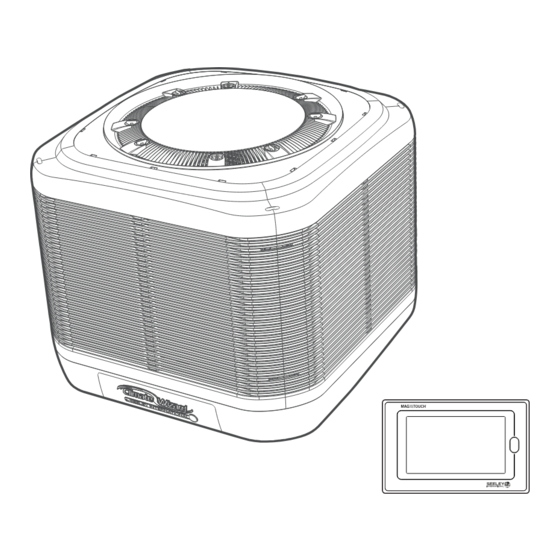
Page 5: Cooler Views
CW logo location Drain Inlet 230mm (9.0”) 346mm Drain (13 5/8”) Inlet 570mm (22 7/16”) suits 530 (20 7/8”) supply duct 570mm (22 7/16”) suits 530mm (20.7/8”) supply duct ILL2678-A ILL2676-A Dimensions are in mm (inches in brackets). 859741-L CW3 INSTALLATION MANUAL... -
Page 6: Exploded View
NUT PIPE FITTING 1.5” BSP 562308 RING MOTOR LOCK 593104 ADAPTOR DRAIN 32-20MM 562046 VENTURI SUPPLY 117928RP CONTROL ASSY 562094 FAN SUPPLY 862758 ELECTRONICS MOUNT PLATE 562186 MOUNT MOTOR SUPPLY 862757 ELECTRONICS SPLASH COVER 562056 VENTURI EXHAUST 122342 FAN EXHAUST 859741-L CW3 INSTALLATION MANUAL... - Page 7 863760 COVER SOLENOID CW3 859713 SOLENOID VALVE SS 12VDC 865615 LEAD ASSY 2C SOLEN 2.220M JST 815979 FILTER WASHER 19mm 3/4” SS 861586 ADAPTOR 3/4-1/2” BSP 816074 COMPRESSION OLIVE KIT 813264 BRASS TUBE 815978 WASHER RUBBER 859741-L CW3 INSTALLATION MANUAL...
-
Page 8: Cooler Contents
Heat/Cool Duct Switch (Australia Only) 134192 Roofstand 0-10 122489 Kit Add On CW3/CW-6S For Roof Stand 134192 ILL2425-B COOLER CONTROLS This cooler is compatible with a wide range of MagIQtouch control solutions, including Wall Controllers, Building Management System (BMS) Controllers and Sensor Accessories. Contact your local Sales office for compatible kits and installation literature. -
Page 9: Transport
Remove the top horizontal timber support members and vertical timber support members. Dispose of responsibly. Leave the base pallet and foam supporting blocks in position in 3 places, as shown. These are required for lifting. ILL2773-B 859741-L CW3 INSTALLATION MANUAL... -
Page 10: Installation
• The cooler must be mounted at least 3m (10’) (preferably 5m (17’)) away from any TV antenna or antenna cables. Make sure the cooler is not between the antenna and the transmission tower that is providing the television signal to the home. 859741-L CW3 INSTALLATION MANUAL... -
Page 11: Mounting / Support
Locate the supply duct transition assembly in installation kit. Roofstands, accommodating 0-10 roof pitches, are available for Temporarily remove both weatherseal flaps as shown. order via Seeley International. See Optional Components List. SUPPLY AIR DUCT PREPARATION ILL2775-A The cooler is designed to be mounted on a supply air duct with Fit the transition onto the supply duct, ensuring that it is outside dimensions of 530 x 530mm (20 7/8”... -
Page 12: Pitched Roof Installation
Lower the supply duct into the opening in the orientation shown. Adjust the position of the supply duct such that the equal angle rests on the high side of the roof. Remove the equal angle after use. ILL2980-A 10 | 859741-L CW3 INSTALLATION MANUAL... -
Page 13: Flashing The Supply Duct
DO NOT USE THE PROVIDED TEK SCREWS – THESE ARE FOR LATER USE ELSEWHERE. ILL2783-A FLASHING THE SUPPLY DUCT The supply duct may now be flashed to the roof. Make sure there is no chance of water entering the roof space. 859741-L CW3 INSTALLATION MANUAL | 11... -
Page 14: Communication Cable Preparation
Pass the non-taped end of the control cable up into the supply duct, through the grommet. Pull the cable through and position it in the transition slot. Leave an excess length of the cable (1.5m or 60” each) hanging out of the supply duct. 12 | 859741-L CW3 INSTALLATION MANUAL... -
Page 15: Cooler Method Of Installation
• Make sure the foam support blocks are firmly inserted upwards into the female openings in the underbody of the tank. ILL3028-A ILL3026-A 859741-L CW3 INSTALLATION MANUAL | 13... - Page 16 Once fitted correctly, the white dropper transition straps should align with the pre-drilled pilot holes in the supply duct. Some transition straps may need to be pulled down to meet with pilot holes in the supply duct. 14 | 859741-L CW3 INSTALLATION MANUAL...
-
Page 17: Communication Cable Installation
ILL3109-A Route the communication cable across the cable tray on the UNDERSIDE VIEW ILL3111-D inner wall of the tank, and then up to the controls module. TOP VIEW ILL3112-A ILL3110-A 859741-L CW3 INSTALLATION MANUAL | 15... -
Page 18: Electrical Requirements
CONTROL MODULE WIRING DIAGRAM INSTALLATION OF THE COOLER MUST CONFORM TO LOCAL ELECTRICAL RULES, REGULATIONS AND STANDARDS. It is a requirement of Seeley International that all coolers be wired with a dedicated circuit and circuit breaker/fuse at the SUPPLY distribution board. -
Page 19: Water Requirements
If alternative water (including rain water) is to be used that contains unusually high or low levels of salinity, hardness, acidity or chemical contaminants, then additional filtration or treatment systems should be employed to render the water ‘potable’. ILL3111-D 859741-L CW3 INSTALLATION MANUAL | 17... -
Page 20: Water Drain Installation
Never drain the water directly onto the roof Important! Drainage systems with long pipe runs, multiple entry points, and/or incorporating traps shall use a tundish or similar air-gap device between the bottom of the drain valve and the drainage system. 18 | 859741-L CW3 INSTALLATION MANUAL... -
Page 21: Cooler Control Components
10 minutes, after which, the inlet solenoid valve opens to refill the reservoir with fresh water. The drain valve will open if it has been 3 days since COOL mode was last run. 859741-L CW3 INSTALLATION MANUAL | 19... -
Page 22: Cooler Control Options
Coolers are supplied with a 20m (66’) control cable. Longer functional. cable lengths are available for order via Seeley International. Note! If a BMS is used, it is suggested that technicians obtain a MagIQtouch Wall Controller as a tool for use during servicing. -
Page 23: Commissioning
□ The water drain installation adheres to all local and national regulations with no leaks at any fittings or valves. □ Drain water pipes/hoses are free from any restrictions (kinks) or blockages. □ The drain water does not discharge onto the roof surface. Signed by Installer: ..............Commissioning Engineer: ............859741-L CW3 INSTALLATION MANUAL | 21... -
Page 24: Magiqtouch Service Menu
□ Set Speed initially to 1 and then progressively increase to 10. □ Check for unusual or excessive sound output at various fan speeds. □ Check for excessive vibration and/or rattle sounds. Signed by Installer: ..............Commissioning Engineer: ............22 | 859741-L CW3 INSTALLATION MANUAL... -
Page 25: Adjusting Cooler Settings
Sets the time delay before the drain valve opens after the pump in the cooler is turned off. AUTOMATIC CLEAN FUNCTION Run a Cooling Core Flush and Tank Drain based on cooler operating time. 859741-L CW3 INSTALLATION MANUAL | 23... -
Page 26: Fault Code Descriptions
No water at Low Probe or Conductivity <9μS/cm 1 Red Flash Water Conductivity < 1500μS/cm 2 Red Flash Water Conductivity < MAX (2305 or 4275 μs/cm). 4 Red Flash 24 Hour Clean Drain Mode Running RED LED TRI-COLOUR LED ILL2465-C 24 | 859741-L CW3 INSTALLATION MANUAL... -
Page 27: Troubleshooting
Heat exchanger cores not fitted correctly into plenum. Check for airgaps around water spreaders and between cores. Water carryover in External static pressure too high. Increase size of ducts. Increase size of room registers/grilles. exhaust airstream. 859741-L CW3 INSTALLATION MANUAL | 25... -
Page 28: Appendix A: Generic Roof Mounting
APPENDIX A: GENERIC ROOF MOUNTING GENERAL NOTES 26 | 859741-L CW3 INSTALLATION MANUAL... - Page 29 APPENDIX A: GENERIC ROOF MOUNTING GENERAL NOTES 859741-L CW3 INSTALLATION MANUAL | 27...
-
Page 30: Timber Truss - 600Mm Spacing
APPENDIX A: GENERIC ROOF MOUNTING TIMBER TRUSS - 600MM SPACING 28 | 859741-L CW3 INSTALLATION MANUAL... -
Page 31: Timber Truss - 1200Mm Spacing
APPENDIX A: GENERIC ROOF MOUNTING TIMBER TRUSS - 1200MM SPACING 859741-L CW3 INSTALLATION MANUAL | 29... -
Page 32: Steel Truss - 600Mm Spacing
APPENDIX A: GENERIC ROOF MOUNTING STEEL TRUSS - 600MM SPACING 30 | 859741-L CW3 INSTALLATION MANUAL... -
Page 33: Steel Truss - 1200Mm Spacing
APPENDIX A: GENERIC ROOF MOUNTING STEEL TRUSS - 1200MM SPACING 859741-L CW3 INSTALLATION MANUAL | 31... -
Page 34: Conventional Roof Framing
APPENDIX A: GENERIC ROOF MOUNTING CONVENTIONAL ROOF FRAMING 32 | 859741-L CW3 INSTALLATION MANUAL... - Page 35 859741-L CW3 INSTALLATION MANUAL | 33...
-
Page 36: Appendix B: 'Piece By Piece' Installation
ILL3034-A Cooler with manifolds removed. ILL2788-A Unclip the spreader hoses and then pull and release the top manifold retention straps. SPREADER HOSES ILL3032-A ILL3130-A RETENTION STRAP TOP ILL3033-A 34 | 859741-L CW3 INSTALLATION MANUAL... - Page 37 ILL3118-A ILL3132-A Leave any remaining wires and hoses connected within the electronics enclosure. Rest the electronics enclosure on the tank in a drained and dry position. 859741-L CW3 INSTALLATION MANUAL | 35...
- Page 38 4 sides and let them hang freely. ILL2797-A Important! This assembly weighs approx. 22kg. Use the appropriate mechanical aids and lifting technique to avoid injury. ILL3133-B Set this assembly aside. ILL3121-A ILL3120-A Cooler with Exhaust Venturi assembly removed. ILL3122-A ILL3115-A 36 | 859741-L CW3 INSTALLATION MANUAL...
- Page 39 Important! This assembly is bulky and weighs approx. 35kg. With a minimum of two persons, transport the bottom half of the cooler to the roof. ILL3124-A ILL3028-A 859741-L CW3 INSTALLATION MANUAL | 37...
- Page 40 Excessive force may cause them to break. Connect the plenum assembly to the supply venturi assembly on the dropper ILL2810-A There should be no gap between the foam and top fan assembly. ILL3185-A ILL2810-A 38 | 859741-L CW3 INSTALLATION MANUAL...
- Page 41 Re-fit cable ties to constrain the cables such that they are suspended above the water. Refit the electronics cable cover and screw to the plenum. ILL2814-A Reconnect the vertical hose pillars to the hose restraint clips on the foam plenums. ILL2815-A 859741-L CW3 INSTALLATION MANUAL | 39...
- Page 42 The panel will lock into place with the lid. For installation of successive side panels, ensure side ribs are neatly interfacing. These can be pressed in with moderate force. ILL2818-A 40 | 859741-L CW3 INSTALLATION MANUAL...
- Page 43 859741-L CW3 INSTALLATION MANUAL | 41...
-
Page 44: Warranty Terms (Australia)
(i.e. names, signature, date, and action taken) when the item is completed. ANY FAILURE TO CARRY OUT THE REQUIRED MAINTENANCE AND SERVICING REQUIREMENTS, AND ANY FAILURE TO PROPERLY FILL OUT THE MAINTENANCE SCHEDULE, WILL VOID YOUR WARRANTY. 42 | 859741-L CW3 INSTALLATION MANUAL... - Page 45 WARRANTY TERMS (AUSTRALIA) In this warranty: We or us means Seeley International Pty Ltd (Seeley) ABN 23 054 687 035, and our contact details are set out at the end of this warranty; You means you, the original end-user purchaser of the Goods;...
- Page 46 PRIVACY NOTICE Seeley International Pty Ltd ABN 23 054 687 035 will use the personal information you provide us with to provide warranty support for the product you have purchased and to inform you about other products and services. If you choose not to supply us with the information requested, we may be unable to provide you with warranty support.
- Page 47 859741-L CW3 INSTALLATION MANUAL | 45...
-
Page 48: Warranty Terms (Usa)
The date the Cooler was commissioned must be provided to Seeley at the time of warranty registration; or (2) If the date the Cooler was originally commissioned cannot be verified by Seeley, the installation date shall be deemed to be the date on the purchaser’s invoice for the purchase of the Cooler. - Page 49 LIMITATION, LOST REVENUES, DOWNTIME, LOSS OF USE, SUBSTITUTE EQUIPMENT, GOODWILL, DAMAGE TO OR REPLACEMENT OF YOUR OTHER EQUIPMENT AND PROPERTY. IN NO EVENT SHALL OUR LIABILITY EXCEED THE PURCHASE PRICE PAID FOR THE GOODS. 859741-L CW3 INSTALLATION MANUAL | 47...
- Page 50 BINDING EFFECT. This Limited Warranty is binding upon and shall inure to the benefit of Convair Cooler Corporation and its parent company, Seeley International Pty Ltd of Australia, which is the manufacturer of the Goods, and which has made a Limited Warranty to SIA that corresponds to this Limited Warranty; and to You and any person directly acquiring title to the Climate Wizard cooler from You whilst in its original place of installation.
- Page 51 859741-L CW3 INSTALLATION MANUAL | 49...
- Page 52 1300 650 644 For outside Australia contact your local dealer It is the policy of Seeley International to introduce continuous product improvement. Accordingly, specifications are subject to change without notice. Please consult with your dealer to confirm the specifications of the model selected.
Need help?
Do you have a question about the CW3 and is the answer not in the manual?
Questions and answers