
Related Manuals for Seeley Climate Wizard CW-H10


Summary of Contents for Seeley Climate Wizard CW-H10
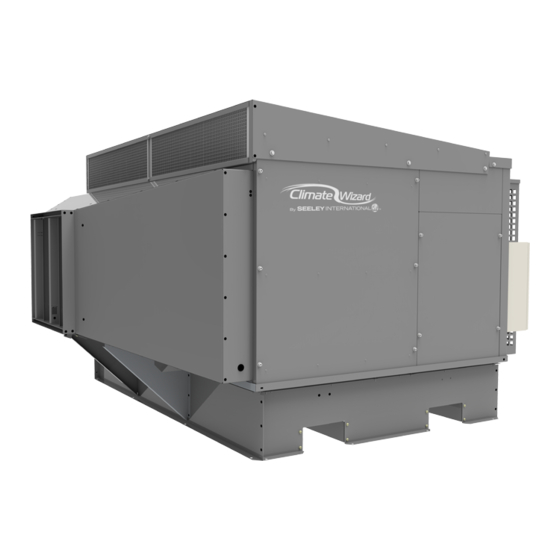
- Page 1 INSTALLATION & OPERATION MANUAL INDIRECT EVAPORATIVE COOLER CW-H10, CW-H15, CW-H15S, CW-H15S Plus 2020 Models (English) (CW-H15) ILL1916 Original English Instructions...
-
Page 3: Table Of Contents
Option 2 Building Management System Low Voltage BMS Interface Terminals Layout And Function Error Status Output Terminal Cooler Operating Mode Input Terminals Fan Speed Input Terminals Cabling Requirements BMS Terminal Connections Example BMS Schematic Option 3 PLC Manual Control SEELEY INTERNATIONAL - INSTALLATION MANUAL 859749-A |... -
Page 4: Important Safety Instructions
Seeley International provides the following in- external switching device, such as a timer, or formation as a guide to contractors and employ- connected to a circuit that is regularly switched ees to assist in minimising risk whilst working at on and off by the utility. -
Page 5: Installer And Maintenance Contractors - Risk Assessment
Is the area below the work area suitably protected to prevent persons walking in this area? Does the work schedule take into ac- • count weather conditions, allowing for SEELEY INTERNATIONAL - INSTALLATION MANUAL 859749-A |... -
Page 6: Cooler Views
COOLER VIEWS ISOMETRIC CW-H10 views shown ILL3157-A ILL3156-A REAR SIDE ILL3159-A ILL3158-A FRONT BOTTOM ILL3160-A ILL3161-A Dimensions are in mm (inches in brackets). CW-H10, H15, H15S, H15S Plus 859749-A... - Page 7 EXHAUST C/L 1171 [46.1] 1283 [50.5] 1150 [45.3] 1700 [66.9] MOUNTING BASE 1800 [70.9] ILL2422-C ILL2422 MOUNTING HOLES BASE FRAME UNDERSIDE [0.394] ILL1920 TYP 16 PL ILL1920-C Dimensions are in mm (inches in brackets). SEELEY INTERNATIONAL - INSTALLATION MANUAL 859749-A |...
-
Page 8: Cooler Exploded View
COOLER EXPLODED VIEW CW-H10, H15, H15S, H15S Plus 859749-A... -
Page 9: Cooler Specifications
* Supply Air Temperatures, Cooling Capacities, COP and Water Consumption tested to Australian Standard AS 2913-2000 and ASHRAE 143 with design condition of: 38 C dry-bulb, 21 C wet-bulb and 27.4 C room exit temperature. FREQUENCY Radiated Sound Power Level (dB(A) re 1pw) Octave Band Centre Frequency Total Sound (Hz) Power dB(A) re 1pw CW-H10 CW-H15 CW-H15S CW-H15S Plus SEELEY INTERNATIONAL - INSTALLATION MANUAL 859749-A |... -
Page 10: Imperial Cw-H Models
COOLER SPECIFICATIONS TECHNICAL SPECIFICATIONS - IMPERIAL CW-H MODELS MODEL: CW-H15 CW-H15S CW-H15S Plus OPTIMUM Airflow Supply Air 2330 CFM @ 2330 CFM @ 3390 CFM @ 0.60 in.w.g. 0.52 in.w.g. 0.32 in.w.g. PERFORMANCE Exhaust Air 1910 CFM 1910 CFM 1270 CFM Temperature* Supply Air 67.1... -
Page 11: Cooler Contents
862801 Conversion Instruction for Supercool units ITEM 10 ITEM 9 ILL2424-B OPTIONAL COMPONENTS ITEM 1 ITEM 2 Seeley Item Description Part 121956 Wall Control Kit 134192 Roofstand 0-10 (CW-H10) 134215 Roofstand 0-10 (CW-H15, H15S, H15S Plus) ILL2424-C ILL2425-B SEELEY INTERNATIONAL - INSTALLATION MANUAL 859749-A |... -
Page 12: Installation
50 x 50 x 3mm (2” x 2” x 1/8”) RHS Galvanized or Painted a corrosion resistant drip tray under the whole machine. Specific CW-H Roofstands are available for order via Seeley Recommended sizes: International to suit cooler size and accommodating 5 or 10 CW-H10: degree roof pitches. -
Page 13: Exhaust Transition Assembly
Ensure any additional ducting is readily removable and/or lightweight. • Where an installation requires extended exhaust ducts, the increase in static load should not exceed 20 Pa (0.08 in wg). ILL2428-A SEELEY INTERNATIONAL - INSTALLATION MANUAL 859749-A |... - Page 14 INSTALLATION The CW-H15S and CW-H15S Plus coolers are fitted with STEP 2 - SET CORRECT DEVICE TYPE Chillcel pads, providing additional Direct Evaporative Cooling (DEC). MODEL CHANGE DEVICE TYPE? CW-H15S They can be configured in two ways; CW-H15S Plus NO - FACTORY DEFAULT MODEL PERFORMANCE SETTING IS CORRECT...
-
Page 15: Water Supply Installation
WATER SUPPLY FILTRATION • Rear Discharge 20mm Push On Hose Seeley International requires an inlet filter to be installed on An access panel can be removed for rear discharge options. the water supply line, external to the Climate Wizard cooler to prevent any debris from entering and damaging cooler components. -
Page 16: Electrical Supply Installation (Australia, Europe - 3Ph 380-415V)
INSTALLATION OF THE COOLER MUST CONFORM TO LOCAL ELECTRICAL RULES, REGULATIONS AND STANDARDS. It is a requirement of Seeley International that all coolers be wired with a dedicated circuit and circuit breaker to the distribution board, incorporating an isolation switch in the fixed wiring with all pole disconnection from the mains power in accordance with the local wiring rules. -
Page 17: Cw-H Control Schemes
OPTION 1 LOCAL ZONE CONTROL WITH WALL CONTROL CW-H coolers can be paired with a Seeley International wall control, supplied separately; Part No.: 121956 The Climate Wizard Wall Controller can control up to a maximum of 7 CW-H cooler acting as a Master Controller over... -
Page 18: Wall Controller / Rs-485 Modbus Node Address
INSTALLATION WALL CONTROLLER / RS-485 MODBUS NODE OPTION 2 ADDRESS BUILDING MANAGEMENT SYSTEM (BMS) LOW Each CW-H cooler on the RS-485 Modbus Network requires a VOLTAGE unique Node Address between 1 and 7. IEC INPUT USER DEC INPUT BUILDING FAN SPEED INPUT MANAGEMENT ERROR OUTPUT SYSTEM... -
Page 19: Error Status Output Terminal
• Tighten screwed terminal connections to 0.6 - 0.8 Nm EXAMPLE BMS SCHEMATIC TEMPERATURE HUMIDITY SETPOINT SETPOINT 0-10VDC 24VDC Contact Open = No Error Contact Closed = Error BMS SYSTEM (BY OTHERS) ILL3621-A SEELEY INTERNATIONAL - INSTALLATION MANUAL 859749-A |... -
Page 20: Commissioning
COMMISSIONING WATER MANAGEMENT SYSTEM Chlorinator Control The Chlorinator is a pair of specially treated plates. When Tank (reservoir) drain valve control energised and submerged in water, electrical current flows • When power switched on to the cooler, the Drain Valve opens. between them generating chlorine. -
Page 21: Setting The Air Discharge Damper
Proceed to balance the external duct and outlets in your usual manner. Check and if necessary re-adjust the Climate Wizard damper back to the above values. Lock the damper in its final position. SEELEY INTERNATIONAL - INSTALLATION MANUAL 859749-A |... -
Page 22: Installation Checklist
INSTALLATION CHECKLIST Owner Name: ................Telephone: ............Address: ......................................Installer: ............Dealer: .............. Model No: ............Date Installed: ..........Serial No: ............INSTALLATION □ The cooler is adequately supported, secure and level. □ The water pipes were flushed of any foreign materials before connection the cooler was made. □... -
Page 23: Maintenance Instructions
Note: Upon exiting TEST MENU, the TEST function is automatically disabled. IMPORTANT: UPON COMPLETION OF SERVICE ENSURE PLC CONTROL IS SET BACK TO ORIGINAL SETTING (W/C OR BMS) ILL3683-A Drain Connection Access Panel ILL3668-A ILL3683-A SEELEY INTERNATIONAL - INSTALLATION MANUAL 859749-A |... -
Page 24: Pump Maintenance & Replacement
MAINTENANCE INSTRUCTIONS PUMP MAINTENANCE & REPLACEMENT SOLENOID VALVE MAINTENANCE AND REPLACEMENT Quantities and locations of pumps for each model. No regular maintenance of the solenoid valve is required. Cores Water Distribution Spreaders Reservoir access Pump Water Inlet Solenoid Access Chlorinator Core Panel Pumps... -
Page 25: Chlorinator Maintenance & Replacement
Use a water hose or low-pressure cleaner to flush all debris down the reservoir drain. After flushing wipe the bottom of the reservoir thoroughly using a wet cloth or brush. SEELEY INTERNATIONAL - INSTALLATION MANUAL 859749-A |... -
Page 26: Drain Valve Maintenance & Replacement
MAINTENANCE INSTRUCTIONS DRAIN VALVE MAINTENANCE AND REPLACEMENT CLEANING OR REPLACING INLET AIR FILTERS The Inlet Air Filters should be and replaced as soon as the SIDE VIEW - RHS airflow through the filters is restricted by dust or contaminants. Cores The frequency of changing the Inlet Air Filters is dependent on Water Distribution Spreaders Reservoir access... -
Page 27: Changing Cooler Cores
They can be placed aside onto the lid of the cooler cabinet OF THE CORES BACK ABOVE THE PATTERN FRONT while still remaining connected to the plumbing system. CHANGES ILL2462-A FAN HOUSING. REAR ILL2458-A ILL2458-A ILL2456-A SEELEY INTERNATIONAL - INSTALLATION MANUAL 859749-A |... -
Page 28: Changing Cooler Chillcel Pads
MAINTENANCE INSTRUCTIONS CHANGING COOLER CHILLCEL PADS Locate the water spreader assembly front flange into the extrusion at top front of the cores. (CW-H15S, H15S Plus ONLY) Remove the cooler cores as per the “Changing Cooler Cores” section. The additional chillcel is located on the supply outlet side of the cooler cores. -
Page 29: Operating And Fault Code Diagnosis
NORMAL RUNNING TRI-COLOUR ON AMBER Note: Both PCBA LEDs are continuously ON once communication between the PLC and PCBA has been established. Failure to establish communication will result in a Fault Code 1. SEELEY INTERNATIONAL - INSTALLATION MANUAL 859749-A |... - Page 30 MAINTENANCE INSTRUCTIONS All faults below shut the cooler down unless stated. Wall Fault Description Suggested Remedy Control Fault Code Fault PLC – PCBA COMMUNICATION FAILURE Check LED status on PCBA. Code 1 Cooler PLC has lost communication with PCBA (Refer to CW-H Manual for further details) fitted inside control box.
- Page 31 Check spreader assemblies securely clamped to top of cores and gaps Core seals/spreaders moved during in exhaust between cores covered up. Check core doors correctly sealing against sides transport. airstream of cores. SEELEY INTERNATIONAL - INSTALLATION MANUAL 859749-A |...
-
Page 32: Maintenance Schedule
MAINTENANCE SCHEDULE Installation 29 /1980 Installer: Date: It is a condition of your warranty cover that the items in the schedule below are checked (and action taken as required) once every 3 months from the date of installation by a qualified, licensed technician, and that the schedule is properly filled out (i.e. name, signature, date, action taken). - Page 33 Duct condition Roof penetrations Mounting & Vibration isolation Access Service No. Service Date Service Technician Service Company No.5 ....................... No.6 ....................... No.7 ....................... No.8 ....................... SEELEY INTERNATIONAL - INSTALLATION MANUAL 859749-A |...
- Page 34 MAINTENANCE SCHEDULE Service Item Check/Adjust Clean Replace Electrical Connections and Component Operation Electrical wiring Fan motor PCBs & Control box Drain valve Water inlet solenoid Water probes Chlorinator Water pump Water Distribution System Water distribution system - hoses and spreaders Water level Cabinet and Accessories Cabinet integrity / leaks...
-
Page 35: Product Warranty
(i.e. names, signature, date, and action taken) when the item is completed. ANY FAILURE TO CARRY OUT THE REQUIRED MAINTENANCE AND SERVICING REQUIREMENTS, AND ANY FAILURE TO PROPERLY FILL OUT THE MAINTENANCE SCHEDULE, WILL VOID YOUR WARRANTY. SEELEY INTERNATIONAL - INSTALLATION MANUAL 859749-A |... -
Page 36: Warranty Terms And Information (Australia Only)
Warranty Details (Australia only) In this warranty: We or us means Seeley International Pty Ltd (Seeley) ABN 23 054 687 035, and our contact details are set out at the end of this warranty; You means you, the original end-user purchaser of the Goods;... - Page 37 The warranty granted in clause 1 covers the costs of parts and labour but you will be responsible for: the cost of travel incurred for a Seeley International service agent to get to and from the location of the Goods if the location of the Goods is either: (i) outside the metropolitan areas of the capital cities;...
-
Page 38: Notes
NOTES This page intentionally left blank. CW-H10, H15, H15S, H15S Plus 859749-A... - Page 40 Seeley International Pty Ltd, 112 O’Sullivan Beach Road, Lonsdale, SA 5160, Australia MANUFACTURED BY: Seeley International Pty Ltd, 77 North Street, Albury, New South Wales 2640, Australia (for Australia, Europe and South Africa) Seeley Acquisition Co., Ltd. doing business as Coolerado, 4430 Glencoe Street,...
Need help?
Do you have a question about the Climate Wizard CW-H10 and is the answer not in the manual?
Questions and answers