
Related Manuals for Seeley Aira AL Series


Summary of Contents for Seeley Aira AL Series
- Page 1 INSTALLATION AND OPERATION AL SERIES EVAPORATIVE COOLER OR MODELS AMI044-A Original English Instructions...
-
Page 3: Table Of Contents
CONTENTS SAFETY OPERATING INSTRUCTIONS 1.0 Introduction 5.1 Startup Single Speed To Provide Cool Air 1.1 General Safety Information 5.2 Startup Single Speed To Provide Ventilation 1.1.1 Handling The Unit 5.3 Shutdown Single Speed Providing Cool Air 1.1.2 Positioning The Cooler 5.4 Shutdown Single Speed Providing Ventilation 1.1.3 Wiring Electrical 5.5 Startup Dual Speed To Provide Cool Air... -
Page 5: Safety
The unit should be installed so that it is level. Allow 1200mm clearance around the unit. Air intake to the unit should not be restricted in any manner. Approval should be sought by Seeley for any installation encroaching on these limits. No modifications shall be made to the unit. -
Page 6: Occupational Health And Safety
SAFETY 1.1.5 Occupational Health and Safety Only safe working practices shall be employed when working on the Al Coolers. The process of installing the units shall take into consideration relevant OH&S requirements. There requirements pertain to all aspects of access, installation, operation and maintenance. -
Page 7: Legionnaires Disease
SAFETY 1.1.10 Legionnaires Disease Evaporative air conditioners have not been implicated in any outbreak of Legionnaires disease, although Legionella bacteria have been found in such systems. The water temperature in the evaporative air cooler section is normally at about 18°C at which temperature the Legionella bacteria (if present) will remain dormant and cannot multiply. The following maintenance schedule is required to be followed in order to comply with the New South Wales Public Health Act 1991 section 46:- a. -
Page 8: General Information
GENERAL INFORMATION 2.1 UNIT OVERVIEW ARIA AL units are Evaporative Coolers. The standard control system is a standalone wall switch or BMS to control the fan and water pumps. Appendix A provides wiring diagrams. When the pumps are turned on water is drawn into the unit and dispersed through the evaporative cooler pads. The fan is then turned on drawing air across the damp pads lowering the temperature of the air before being fed into the duct work. -
Page 9: Technical Specification
• All units are available at order with 2 different motor power capacity to meet flow and pressure requirements. Units may be fitted with a larger motor at additional cost. Contact Seeley international for further advice. • Axial fans are specified for the F configuration and designed to be installed indoors generally as an air curtain. -
Page 10: Drainage
GENERAL INFORMATION 2.5.8 Drainage All AL coolers require adequate drainage to remove water from the unit. It is the installers responsibility to ensure that the drain is adequately sized to accommodate the unit. The local drains shall be sufficient to remove the excess water required to clean out the unit as required. -
Page 11: Installation Information
INSTALLATION INFORMATION 3.0 INSTALLATION INFORMATION The supplied units are to be installed in accordance to this manual, relevant local standards, acts and regulations. Before installation it is the customers responsibility to ensure that the water and electrical supply required by the unit is available and that the building structure is sufficient to support the load of the operational unit and service and installation personal. -
Page 12: Model Variations And Dimensions
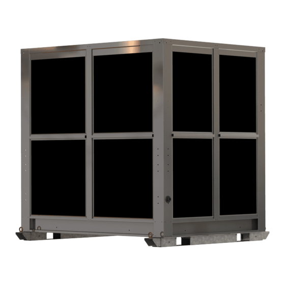
INSTALLATION INFORMATION 3.1 MODEL VARIATIONS AND DIMENSIONS AL SERIES COOLERS TOP (AL18, AL25, AL30) ISOMETRIC (AL18, AL25, AL30) 110.8 110.8 AMI133-A TOP AMI133-A ISO REAR (AL18, AL25, AL30) SIDE (AL18, AL25, AL30) 110.8 110.8 AMI133-A REAR AMI133-A SIDE FRONT (AL18, AL25, AL30) BOTTOM (AL18, AL25) 110.8 110.8... -
Page 13: Cooler Dimensions (Al18, Al25, Al30, Al36)
INSTALLATION INFORMATION 3.1.1 COOLER DIMENSIONS (AL18, AL25, AL30, AL36) AL18 AL25 AL30 AL36 1550 1890 2230 1550 1550 2240 1250 1570 1920 2135 1090 1090 Table 1: AL Series Cooler Dimensions AL SERIES COOLERS ISOMETRIC (AL36) TOP (AL36) AMI145-A ISO AMI145-A TOP REAR (AL36) SIDE (AL36) -
Page 14: Drain Location Dimensions (Al18, Al25, Al30, Al36)
INSTALLATION INFORMATION 3.1.2 DRAIN LOCATION DIMENSIONS (AL18, AL25, AL30, AL36) Model AL18 AL25 AL30 AL36 Table 2: Drain Location Dimensions (mm) Figure 5: Drain Location AMI101-A... -
Page 15: Installation
INSTALLATION INFORMATION 3.2 INSTALLATION The following recommendations are not intended to supplant or take precedence over relevant official regulations. AIRA AL Evaporative Cooler units are designed essentially as a roof top or external ground mount unit. 3.2.1 Location This equipment is not designed for long and complex air distribution ductwork and as such the unit should be located as close as practicable to the points of air distribution. -
Page 16: Clearance Around Unit
INSTALLATION INFORMATION 3.2.2 Clearance Around Unit 1200mm is the recommended clearance around all sides for service access. Figure 6: Service Clearance around Unit AMI102-A 3.2.3 Plant Room It is not recommended to install an AL Evaporative Cooler in an enclosed plant room. Doing so may introduce negative pressure into the plant room and allow for harmful gases and fumes to be pulled into the building creating a risk to the building occupants. -
Page 17: Weight And Location
Below is a suggested lifting arrangement. Noting that the centre of gravity should be assessed for each unit prior to rigger lifting. By suitably qualified crane operator, and dogmen. Certification of the lifting lug assembly may be obtained by contacting Seeley International. Figure 9: Lifting Example AL SERIES INSTALL OPERATION MAINTENANCE MANUAL |... -
Page 18: Positioning And Securing
INSTALLATION INFORMATION 3.2.7 Positioning and Securing Cabinet units are supplied with under cabinet skids. Units are designed to be supported along the length of the skids. Holes may be drilled into the skids to secure the unit in place. Lifting points at either end of the units are NOT to be used for anything other than lifting the unit into place and may be removed once installation has occurred. -
Page 19: Electrical Connections
INSTALLATION INFORMATION 3 ELECTRICAL CONNECTIONS 3.3.1 Electrical Supply All electrical connections are to be as per AS3000. All electrical work shall be performed by a registered electrical contractor. Appendix A: Electrical Information, provides a comprehensive electrical connection guide including wiring configurations for different control setups and wiring diagram package and should be used in conjunction with this manual. -
Page 20: Water Connections
INSTALLATION INFORMATION 3.4 WATER CONNECTIONS 3.4.1 Water Supply The supply pipe should be suitably sized to meet the specified flow and pressure. A ¼ turn ball isolating valve must be installed on the supply pipe near the unit for ease of maintenance. Do not use duo or non-return (check) valves of any kind including stop taps with jumper washers. -
Page 21: Drain
INSTALLATION INFORMATION 3.4.3 Drain The combination drain/overflow pipe outlet must be connected to a drainpipe with sufficient capacity to take the discharge of water from the reservoir. The pipe must connect to a suitable drain or gutter. Drain must be lower than base of pad assembly. -
Page 22: Cooling Pads
INSTALLATION INFORMATION 3.4.6 Cooling Pads All units have removable cooling pads that provide access to the internal components of the cooler. The following steps can be used to remove cooling pads. 1. Confirm that the unit is not operating and that the power is isolated. Do not remove pads whilst the unit is operational. -
Page 23: Commissioning Information
COMMISSIONING INFORMATION 4.0 COMMISSIONING Prior to commencement ensure Main Isolator Switch is OFF and correct electrical Lock Out Tag Out (LOTO) procedures are followed. Failure to do so may result in Injury or Death. A commissioning report template is available in Appendix D of this document. AS5601.1 Appendix O provides additional guidelines for commissioning. - Page 24 COMMISSIONING INFORMATION Confirm the fan direction. If the fan is spinning in reverse, check the wiring diagram to ensure that the motor is wired in correctly. Fan direction is to be checked on high and low settings.
-
Page 25: Water Checks
11. Check belt tensions and pulley alignment and adjust if necessary. Check to ensure that the blower wheel has not shifted. If unsure please contact a Seeley International service agent. 12. Ensure that a maintenance schedule is prepared in accordance with suppliers’ recommendations and requirements of local authorities. -
Page 26: Setting Pad Saturation
2. If the unit is new, then the pump flow rate adjuster/tap will likely be found to be in the ½ open position. 3. The evaporative unit must be installed, plumbed and float levelled as per Seeley International instructions. The airflow rate should be adjusted to meet specifications. -
Page 27: Operating Instructions
OPERATING INSTRUCTIONS 5.1 STARTUP SINGLE SPEED – WALL SWITCH UNITS TO PROVIDE COOL AIR 1. Switch the FAN switch to ON. 2. Switch the COOL switch to ON. 3. Switch the Wall Switch ON/OFF switch to ON. 5.2 STARTUP SINGLE SPEED - WALL SWITCH UNITS TO PROVIDE VENTILATION 1. -
Page 28: Operational Flowchart
OPERATING INSTRUCTIONS 5.10 OPERATIONAL FLOWCHART Water and Wall Switch is Electrical supplied to the unit Turn ON/OFF Switch to ON Single Speed Dual Speed Units Only. room begins. Units Only. Switch FAN Select Fan switch to ON Speed HIGH/ Water Pump begins to draw Switch COOL water into the cooling pads switch to ON... -
Page 29: Maintenance
WARNING! Aira AL units require electrical and plumbing trades to service all aspects of the unit. Servicing should be carried out by a qualified Seeley International Service Technician, appointed Aira service agent or appropriately AMI055-A qualified trades persons. If unsure about any servicing or maintenance aspect of the unit, immediately stop work and contact Seeley International for assistance. -
Page 30: Major Service/Component Replacement Process
Motors range in weight from approximately 20 to 270Kg’s. Generally the larger the unit the larger the motor. Refer to technical data sheet or contact Seeley International with the units serial number to identify which motor you have. The use of a lifting apparatus and/or several service personnel may be required for heaver motors. -
Page 31: Belts
All mount bolts should be high tensile and a minimum grade of 8.8. Anti-seize should be used on all stainless steel bolts. c). Belt Tensioner recommended when replacing/reinstalling belts. d). This is ONLY applicable to units with a Seeley supplied blower box. 3rd Party blowers will have their own maintenance schedule. 6.2.1.7 Fan Direction Check that the fan is blowing in the right direction. -
Page 32: Water Components
MAINTENANCE 6.2.2 Water Components 6.2.2.1 Water Controls Confirm that the incoming water supply isolation valve is operational. If the isolation valve is in a location accessible by the public ensure that the valve can be locked open and closed. 6.2.2.2 Water Connection Visual Inspection The incoming water supply is to be visually inspected for damage and leaks. -
Page 33: General Installation
MAINTENANCE 6.2.3.4 General Installation Visually inspect the mounting and how the unit is secured to the roof/ground. Ensure that the unit is stable and correctly aligned with the ductwork. 6.2.4.5 Access to Unit Check that access to the unit is free of obstructions. If the unit is located on a roof and an anchor system and harness are certified and maintained by an appropriately qualified individual. -
Page 34: Fault Finding Cooler
Replace with new filter pads. Check restrictor tap setting and adjust if required. Table 6: Fault Finding Coolers 6.4 REPLACEMENT PARTS LIST Contact Seeley Spare Parts for comprehensive spare parts list, Model and Serial Number will be required. -
Page 35: Appendix A: Electrical Information
APPENDIX A: ELECTRICAL INFORMATION APPENDIX A1 - 3 PHASE WIRING DIAGRAM AL SERIES INSTALL OPERATION MAINTENANCE MANUAL |... -
Page 36: Appendix A2 - 3 Phase Cooler Auto Drain Wiring Diagram
APPENDIX A: ELECTRICAL INFORMATION APPENDIX A2 - 3 PHASE COOLER AUTO DRAIN WIRING DIAGRAM... -
Page 37: Appendix B: Commissioning Report
APPENDIX B: COMMISSIONING REPORT Pass = Adjust = A Attention Req. = X Model Number Serial Number Unit Details Installer Installation Date Site Address Unit Condition Access to the Unit Condition of Casing Unit is adequately secured Structural bolts and grub screws tight General Installation Roof Stand Installation Duct Work to unit connected... - Page 38 APPENDIX B: COMMISSIONING REPORT Commissioning Notes:...
-
Page 39: Appendix C: Maintenance
APPENDIX C: MAINTENANCE APPENDIX C1: MAINTENANCE SCHEDULE DESCRIPTION COMPONENT Month Month Month Month Month Month Month Month Month Month Month Month Pre- Season Electrical Incoming Electrical Supply Electrical Wiring ... -
Page 40: Appendix C2: Monthly Maintenance Check
APPENDIX C: MAINTENANCE APPENDIX C2: MONTHLY MAINTENANCE CHECK Owner Monthly Checklist Unit Type: ______________________ Description Component Check For C=Clean R= Replace A= Adjust √= Check Electrical Incoming Electrical Visually inspect incoming electrical supply Supply and isolation for signs of damage. Water Incoming Water Visually inspect incoming water connection for... -
Page 41: Appendix C3: Maintenance Checklist
APPENDIX C: MAINTENANCE APPENDIX C3: MAINTENANCE CHECKLIST Maintenance Check List Unit Type: ______________________ Date of Maintenance: ___________________ Description Component Check For C=Clean R= Replace A= Adjust = Check N/A= Not Required Electrical Incoming electrical Visually inspect incoming electrical supply supply and isolation for signs of damage. - Page 42 APPENDIX C: MAINTENANCE Installation Access to unit Access to unit is clear of obstructions. Roof anchor system is compliant and certified if required. Casing Check that the case is free of damage. Check that all access panels are secure. Check the internal of the cases for signs of water build up.
-
Page 43: Appendix D: Warranty Information
APPENDIX D: WARRANTY INFORMATION D1 - HOW TO REGISTER YOUR PRODUCT WARRANTY (AUSTRALIA AND NEW ZEALAND ONLY) Warranty Information section HOW TO REGISTER YOUR PRODUCT WARRANTY (Australia and New Zealand only) Please register your warranty online by visiting seeleyinternational.com and selecting COMMERCIAL section on the top right hand side of the screen. -
Page 44: D2 - Warranty Terms And Information
Warranty Details (Australia and New Zealand only) In this warranty: We or us means Seeley International Pty Ltd (Seeley) ABN 23 054 687 035, and our contact details are set out at the end of this warranty; You means you, the original end-user purchaser of the Goods;... - Page 45 11. This warranty is only valid and enforceable in Australia. Note: It is important that the safety and privacy of our service technicians is protected at all times. Accordingly, We and our Seeley International service agents reserve the right to refuse service if (i) safety and accessibility to the unit cannot be guaranteed or (ii) the owner of the unit, occupant of the site where the Goods are located, or any other third party seeks to take photographs, or make a video or audio recording, of the service technician(s) while they are on the site or carrying out service to the unit.
- Page 46 PRIVACY NOTICE Seeley International Pty Ltd ABN 23 054 687 035 will use the personal information you provide us with to provide warranty support for the product you have purchased and to inform you about other products and services. If you choose not to supply us with the information requested, we may be unable to provide you with warranty support.
-
Page 47: Appendix E: Release Information
APPENDIX E: RELEASE INFORMATION Date Amendment Author Approved 01-06-2017 Initial Release T. Zahtila Updated Format Updated General Information Added Installation Information Added Commissioning Information 13-12-2018 Updated Operating Instructions R. Aisbett C. Arnel Added Unit Maintenance Information Added Appendix A Added Appendix B Added Appendix D 3-4-2019 Updated Operating Instructions... - Page 48 MANUFACTURED BY: SEELEY INTERNATIONAL PTY LTD 77 NORTH ST, ALBURY NSW 2640, AUSTRALIA It is the policy of Seeley International to introduce continuous product improvement. Accordingly, specifications are subject to change without notice. Please consult with your dealer to confirm the specifications of the model selected.
Need help?
Do you have a question about the Aira AL Series and is the answer not in the manual?
Questions and answers