Sime MURELLE REVOLUTION 30 User, Installation And Servicing Instructions
Hide thumbs
Also See for MURELLE REVOLUTION 30:
- User, installation and servicing instructions (100 pages)
Chapters
Table of Contents

Related Manuals for Sime MURELLE REVOLUTION 30


Summary of Contents for Sime MURELLE REVOLUTION 30
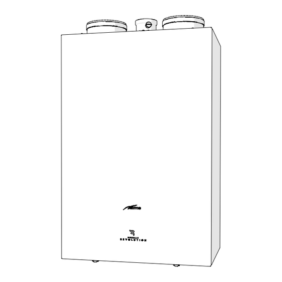
- Page 1 Cod. MURELLE REVOLUTION 30 USER, INSTALLATION AND SERVICING INSTRUCTIONS To consult the documentation, visit our website www.sime.it Fonderie SIME S.p.A. 6328587A - 08/2022 - R4 TRANSLATION OF THE ORIGINAL INSTRUCTIONS...
- Page 2 – This manual is an integral part of the – The appliance must be used as intend- appliance. It must therefore be kept ed by Sime who is not responsible for for future reference and must always any damage caused to persons, ani-...
- Page 3 RESTRICTIONS IT IS FORBIDDEN IT IS FORBIDDEN – To allow children under the age of 8 to – To block the condensate drain. use the appliance. The appliance can – To pull, detach or twist the electrical be used by children no younger than cables coming out of the appliance 8 years old, by people with physical even if the appliance is disconnected...
- Page 4 Dear Customer, MANUAL STRUCTURE Thank you for purchasing a Sime Murelle Revolution 30 boiler, This manual is organized as follows. a new-generation modulating hybrid condensing device pos- sessing technical and performance characteristics capable of satisfying your space heating and instant domestic hot water USER INSTRUCTIONS requirements with the utmost safety and limited running costs.
-
Page 5: Table Of Contents
USER INSTRUCTIONS TABLE OF CONTENTS USING THE BOILER MURELLE REVOLUTION 30 MAINTENANCE Main control panel (remote) ..... . . 6 Adjustments. -
Page 6: Main Control Panel (Remote)
USING THE BOILER MURELLE REVOLUTION 30 Main control panel (remote) The main control panel (MCP) allows all of the necessary adjustments to be made to Murelle Revolution 30 and to the connected sys- tems. It also serves as a main air thermostat and can therefore be used by all operators, users, authorised maintenance technicians and the technical service for the operations for which each of these figures is authorised, as described in detail in the relevant sections. -
Page 7: Start-Up
INFORMATION [...] tective gloves. TECHNICAL [...] Commissioning of the Murelle Revolution 30 boiler must be car- Back ried out by professionally qualified technicians, after which the Fig. 3 boiler can operate automatically. It may, however, be necessary for the user to start the appliance autonomously without involv- ing a technician: for example, after a holiday. -
Page 8: Settings Using The Mode Button
Settings using the MODE button – press the encoder to confirm the highlighted “Mode” click From the “Main screen”: and go to the “rows” – Turn the encoder to “Boiler” Zone Thu 18 Set 2014 10:30 INFORMATION INFORMATION Zone heating [...] Zone heating [...]... -
Page 9: Time Programming
– turn the encoder to select the “Single days” or the “Group of days” Heating Function Mode Set AUTO comfort 20.0°C – press the click encoder to confirm the required selection Set AUTO reduced 18.0°C and access the first “Adjustable time” [1] Set MAN 20.0°C Program. -
Page 10: Holiday Function
1.3.2 Holiday function : The user must work in a CIRCULAR manner, meaning AL- NOTE This function allows the user to deactivate both heating and hot WAYS MOVING FORWARDS, even if a mistake is made. water production during a “set and activated” holiday period, during which the antifreeze function can be active (if set). -
Page 11: Quick Settings
1.3.4 Quick settings – turn the encoder to set the new “Set value” The encoder allows the operator, specifically the user, to: – press the button to complete the modification Confirm – change the “Set hot water” in SUMMER mode and return to the “Main screen”. -
Page 12: Maintenance
MAINTENANCE DISPOSAL Adjustments Disposal of the equipment (European Di- rective 2012/19/EU) For the appliance to operate correctly and efficiently it is recom- mended that the User calls upon the services of a Professionally At the end of their life span, the appliance Qualified Technician to carry out ANNUAL maintenance. - Page 13 DESCRIPTION OF THE APPLIANCE TABLE OF CONTENTS Main water circuit ......21 DESCRIPTION OF THE APPLIANCE Sensors.
-
Page 14: Description Of The Appliance
After a set period of time, calculated using an algorithm ac- probe is NOT connected, Murelle Revolution 30 will NOT work. cording to the current outdoor temperature, the gas boiler also... -
Page 15: Check And Safety Devices
Check and safety devices Identification The Murelle Revolution 30 boilers are equipped with the following The Murelle Revolution 30 boilers can be identified by means of: check and safety devices: this is located on the outside of the packag- Packaging label: –... -
Page 16: Technical Data Plates
4.4.1 Technical data plates Heat Pump Technical Data Plate Fonderie Sime SpA Legnago VR (Italy) Tel 0442 631111 POMPA DI CALORE ARIA/AQUA PER RISCALDAMENTO AIR TO WATER HEAT PUMP FOR HEATING SYSTEM Modello Matricola NAME SERIAL NUMBER SM16021614019 MURELLE REVOLUTION Alimentaz. -
Page 17: Structure
Structure Air inlet pipe Domestic hot water filter Gas boiler smoke evaporator Condensate siphon System relief valve Heat exchanger bleed point Diverter valve Boiler drain Heat exchanger System filling unit System pump Smoke flue gas probe Domestic hot water sensor Water pressure transducer Combustion chamber door Boiler control panel (gas side) - Page 18 System filling valve HP high pressure switch Condensate outlet HP low pressure switch Safety valve outlet Liquid level indicator Boiler connector (gas side) – Main Boiler drain control panel Thermostatic expansion valve HP-main control panel connector HP by-pass solenoid valve Fig.
-
Page 19: Technical Features
Technical features 4.6.1 Boiler (gas side) DESCRIPTION Murelle Revolution 30 CERTIFICATIONS Country of intended installation IT – ES – PT – GR – SI – CZ – CH – GB – IE – SK – LT – HR Fuel G20 / G31... -
Page 20: Heat Pump
DESCRIPTION Murelle Revolution 30 NOZZLES - GAS Number of nozzles Nozzle diameter (G20-G31) Gas consumption at Max/Min flow rate (G20) 2,96 / 0,42 Gas consumption at Max/Min flow rate (G31) Kg/h 2,17 / 0,31 mbar 20 / 37 Gas supply pressure (G20/G31) -
Page 21: Main Water Circuit
Main water circuit Fig. 35 KEY: Pump M System delivery Automatic bleed valve R System return Pressure transducer U Domestic hot water outlet System expansion vessel E Domesti hot water inlet HP water inlet probe S Safety valve outlet System delivery valve (on request) G Gas supply Gas valve (on request) Condensate outlet... -
Page 22: Sensors
Sensors 4.10 Circulation pump The sensors installed have the following characteristics: The flow-head performance curve available for the heating sys- – Dual sensor (thermal safety/output) NTC R25°C; 10kΩ β25°- tem is shown in the graph below. 85°C: 3435 – domestic hot water sensor NTC R25°C; 10kΩ β25°-85°C: 3435 RESIDUAL HEAD (mbar) –... -
Page 23: Boiler Control Panel (Gas Side)
4.10.1 Boiler control panel (gas side) pressing any one of these buttons for more than 30 sec- NOTE: onds generates a fault on the display without preventing boiler The boiler control panel can be used locally ONLY by the technical operation. -
Page 24: Heat Pump Control Panel (Local)
4.11 Main control panel (remote) The main control panel (MCP) allows all of the necessary adjustments to be made to Murelle Revolution 30 and to the connected sys- tems. It also serves as a main air thermostat and can therefore be used by all operators, users, authorised maintenance technicians and the technical service for the operations for which each of these figures is authorised, as described in detail in the relevant sections. -
Page 25: Using The Buttons
4.11.1 Using the buttons BUTTON (B) This allows users to view the “Function mode” screen (e.g. “Win- With the appliance powered, from the “Main screen”. ter”) and then to operate according to what is written above the button on the display (e.g. to exit and return to the main screen). -
Page 26: Wiring Diagrams
4.12 Wiring diagrams 4.12.1 Boiler 4 3 2 1 CN12 CN13 CN15 CN14 CN11 Y - G OT OTSE SE Line Blue Neutral Fuse (3.15AT - 250V) Brown Diverter valve Smoke flue gas probe Black System pump Safety thermostat Green Return Probe Delivery sensor Grey... -
Page 27: Heat Pump
4.12.2 Heat pump BY-PASS 4 3 2 1 COMP RS485 COND 230 V - 50 Hz Heat pump fan Main control panel (remote) Blue By-pass solenoid valve 24V power supply Brown BY-PASS Fan check probe Fuse (2AT) Black System return probe Fuse (500mAT) Green System delivery probe... -
Page 28: Interconnecting The Appliance, Outdoor Probe And Main Control Panel (Remote)
4.12.3 Interconnecting the appliance, outdoor probe and main control panel (remote) The connections below should be made by the installer and must be prepared before installing the main control panel (remote), See " Mounting the main control panel (remote)". OT OTSE SE Unpolarised cable Shielded polarised cable Shield connected to earthing system on both sides... - Page 29 Malfunction codes and possible solutions ..63 5.15.2 EMPTYING operations ....42 MURELLE REVOLUTION 30 CHECKLIST COMMISSIONING Preliminary operations .
-
Page 30: Using The Boiler Murelle Revolution
INSTALLATION CAUTION The appliance must only be installed by the Sime Tech- nical Service or by qualified professionals who MUST suitable protective safety equipment. wear Receiving the product Murelle Revolution 30 is delivered in a single unit protected by cardboard packaging. -
Page 31: Installation Room
Fig. 52 New installation or installation of a re- placement appliance When Murelle Revolution 30 boilers are installed on old systems or systems requiring updating, it is recommended the installer checks that: – the connecting flue pipe is suitable for the combustion tem-... -
Page 32: Cleaning The System
Boiler installation Before mounting the Murelle Revolution 30 boiler on the wall, check that: – the wall is solid enough to support the weight – the required minimum clearance zones are respected –... -
Page 33: Plumbing Connections
5.11 Gas supply boilers leave the factory prearranged for Murelle Revolution 30 gas G20 and can also work with G31 without the need for any type of mechanical conversion. Simply select parameter "03" (see “Parameter setting and display") and set the type of gas * 64,5 to be used. -
Page 34: Smoke Outlet And Air Inlet (Combustion/Heat Pump)
WARNINGS where the appliance will be used. boilers must be installed and Murelle Revolution 30 – The use of rigid ducts which are resistant to tem- used with smoke outlet ducts and combustion/heat perature, condensate, mechanical stress and are pump air inlet ducts fitted as specified below. -
Page 35: Holes For Air Inlet/Outlet
5.12.2 Holes for air inlet/outlet Two holes are required for the appliance in the wall to channel the air inlet (1) and outlet (2) pipes outside. ≈3° Fig. 61 WARNING When making the holes for channelling the inlet and outlet pipes outside, the majority of the material may be expelled outside;... -
Page 36: Smoke Outlet (Ø 80 Mm)
5.12.4 Smoke outlet (Ø 80 mm) Example calculation of the load loss of a smoke outlet for a Mur- boiler. elle Revolution 30 (installation permitted since the total of the load loss of the ac- cessories used is less than 15 mmH Load loss (mm Accessories Ø... -
Page 37: Electrical Connections
– refit the user interface (3) on the base (2), hooking the tab (1) on correctly. If this cable needs to be replaced, an original spare must be re- quested from Sime . DESCRIPTION CODE Power cable (dedicated) 6127260 Fig. -
Page 38: External Temperature Sensor
– press the encoder to access the modifiable area. The click requires an outdoor probe. This is supplied Murelle Revolution 30 following screen is displayed: and MUST be connected because the boiler uses the outdoor temperature detected to operate. CONFIRM REQUEST... -
Page 39: Chrono-Thermostat Or Air Thermostat For The Zone
– turn the encoder to select the “Climatic curve ” row Winter Summer Zone heating Hot water MAN 40°C Req. from ext. TA Heating MAN 20.0°C Room probe run Room probe modul. Holiday function Ext. probe modul. Back Weather comp.curve ˆ... -
Page 40: Example Of Use Of The Command/Control Device On Some Types Of Heating Systems
From the “Main screen”: – press the encoder to access the modifiable parame- click ters area Zone Thu 18 Set 2014 10:30 Zone heating Req. from ext. TA Room probe run Room probe modul. Ext. probe modul. Menu Mode Weather comp.curve Fig. -
Page 41: Refilling Or Emptying
Fig. 90 MULTI ZONE system – with zone valve and air thermostats. 5.15.1 REFILL operations The Murelle Revolution 30 boilers are not equipped with a filling valve which must be prearranged on the system return. The pro- cedure is described below. -
Page 42: Emptying Operations
5.15.2 EMPTYING operations Domestic hot water circuit: – open the isolation valves of the domestic hot water circuit (if Domestic hot water circuit: present) – close the domestic hot water circuit isolation valve (prear- – open one or more than one hot water valve to fill and bleed the ranged in installation) domestic hot water circuit –... -
Page 43: Commissioning
COMMISSIONING – disconnect and reconnect the electrical power supply by set- Preliminary operations ting the main system switch to “OFF” and then to “ON” WARNING – Should it be necessary to access the areas in the bottom part of the appliance, make sure that the system components and pipes are not hot (risk of burning). -
Page 44: Main Control Panel Display And Settings
For any – the values flash on the display: "100" (maximum value), fol- lowed by an "intermediate value" and finally "00" (minimum specific support, please contact the Sime Technical Assistance Service. value) 6.3.1 Settings using the MODE button From the “Main screen”:... -
Page 45: Fault Warnings
The fault may be transient (volatile) or it may cause an appliance block – turn the encoder to select “Heating” (Heating) – press the click encoder to confirm “Heating” and access the To restore normal operating conditions: “Rows” – if the fault is transient, eliminate the cause of the fault –... -
Page 46: Navigating Using The Mode Button
6.3.2 Navigating using the MODE button Modo: Inverno Progr. automatico - Set 18,0 Cfino alle 11:30 Menu Mode MODE To “select” rows or “modify” values click To “confirm” the selections or modifications Summer Winter Hot water HOLIDAY SCHEDULE Function mode MONTH YEAR Hour... -
Page 47: Settings Using The Menu Button
6.3.3 Settings using the MENU button – turn the encoder and modify the “Data/value” in the 6.3.3.3 GENERAL SETTINGS menu permitted field (e.g. from ENG to ITA) From the “Main screen” on the main control panel (MCP) , proceed as follows: GENERAL SETTINGS Language Date and time... - Page 48 The “Display" menu allows the user to adjust: – display contrast – press the encoder to confirm the highlighted submenu click – duration of the display back-lighting and access the modifiable area – encoder back-lighting The operating procedure is as has been described so far. SETTING DATE AND HOUR MONTH YEAR...
-
Page 49: Information Menu
CAUTION Fig. 124 We recommend not changing the factory settings so as not to alter optimal appliance operation. For any specific support, please contact the Sime Technical – turn the encoder to select the required submenu Assistance Service. – press the... - Page 50 CAUTION – press the button to view the “Menu” selection Menu screen When the submenu “Boiler parameters” is selected, the following screen appears when the encod- – turn the encoder to select the “TECHNICAL” menu click er is pressed: MENU GENERAL SETTINGS [...] ENTER ACCESS CODE...
-
Page 51: Technical Assistance Centre Menu
If the value of the selected parameter is to be modified: – press the encoder to confirm click – press the click encoder to access the value modification area CUSTOMER SERVICE NAME: PHONE: Boiler parameters Parameter Index: 1 1--------49 Parameter Value: 0 Cancel Confirm Fig. -
Page 52: Navigating Using The Menu Button
6.3.4 Navigating using the MENU button Modo: Inverno Progr. automatico - Set 18,0 Cfino alle 11:30 Menu Modo MENU “select” rows or “modify” values MENU MENU click the selections or modifications “confirm” GENERAL SETTINGS GENERAL SETTINGS [...] [...] INFORMATION [...] INFORMATION [...] TECHNICAL... -
Page 53: Parameter Setting And Display
Parameter setting and display – turn the encoder to select the required submenu To access the parameters menu from the “Main screen” : – press the click encoder to confirm the selected submenu and access the modifiable parameters area. Zone Thu 18 Set 2014 10:30 NOTE... - Page 54 Range Step Default CONFIGURATION Index showing boiler power in kW 6 = 30 (MURELLE REVOLUTION 30) 0 = rapid 1 = storage tank with thermostat or heating only Hydraulic configuration 2 = hot water tank with sensor 3 = bithermic...
- Page 55 Type Description Range Step Default Minimum Heating Temperature 20 .. PAR 14 °C Adjustment Maximum Heating Temperature PAR 13 .. 80 °C Adjustment Maximum power heating 0 .. 100 seconds Heating Post-Circulation Time 0 .. 99 x 10 seconds Heating Pump Activation Delay 0 ..
-
Page 56: Fault / Malfunction Codes
Fault / malfunction codes Type Description Incorrect positioning of the delivery sensor If a fault occurs, the screen “Anomaly in progress” (Fault in pro- EV2 SGV current max/min absolute limits error gress) will appear in place of the “main screen”. For the main EV2 SGV current upper limit error fault codes, a brief description and suggestions for the user are EV2 SGV current lower limit error... -
Page 57: Display Of Operating Data And Counters
TABLE OF INFORMATION DISPLAYED Display of operating data and counters Type Description Range Step Once the boiler is operating a qualified technician can view the SW version operating data and the counters as follows:> External - 9 .. – from the boiler control panel screen (gas side) in the mode °C temperature sensor Delivery sensor... -
Page 58: Checks
Checks 6.7.1 Chimney sweeper function The chimney sweeper function is used by the qualified mainte- nance technician to check the mains gas pressure, detect the combustion parameters and to measure the combustion effi- ciency required by legislation in force. This function lasts 15 minutes and is activated by proceeding as follows: –... -
Page 59: Domestic Hot Water Comfort Function (Preheating)
– press the button to exit the "Chimney sweeper Proce- The Murelle Revolution 30 models can work at G20 or at G31 dure”. The boiler water delivery temperature will appear on without any mechanical transformation. It is necessary to select the display parameter "PAR 03"... -
Page 60: Maintenance
MAINTENANCE Adjustments Cleaning the inside of the appliance For the appliance to operate correctly and efficiently it is recom- 7.3.1 Removing components mended that the User calls upon the services of a Professionally Qualified Technician to carry out ANNUAL maintenance. To access the internal parts of the boiler: –... -
Page 61: Cleaning The Burner And The Combustion Chamber
– remove the two screws (7), lift the expansion vessel and hook – Unscrew the four nuts (14) securing the combustion chamber it onto the support (8) door (15) – pull the fan/sleeve/door/air pipe assembly (16) forwards and remove it. Fig. -
Page 62: Cleaning The Smoke Exchanger
7.3.4 Cleaning the smoke exchanger Checks Remove the cover (17) by unscrewing the two screws and re- 7.4.1 Checking the smoke duct move any carbon deposits. Check that the combustion air inlet/outlet ducts and smoke out- let duct are integral and airtight. 7.4.2 Checking the expansion vessel pressure It is recommended that the expansion vessel on the water side... -
Page 63: Unscheduled Maintenance
- Replace the pump Revolution 30 - Check PAR 02 "hydraulic Index showing boiler power in kW Auxiliary sensor configuration" 6 = 30 (MURELLE REVOLUTION 30) fault - Check the electrical connection Hydraulic configuration Gas valve 0 = rapid modulator... - Page 64 Heat pump fault Type Fault Solution Type Description Solution Block due to Automatic reset numerous - Check electrode Remove and reconnect combustion - Check outlets High pressure the electrical power control failures supply Flow rate reduced Automatic reset for (presumed) low - Check gas flow rate Remove and reconnect pressure on mains...
-
Page 65: Murelle Revolution 30 Checklist
CHECKLIST MURELLE REVOLUTION 30 The Murelle Revolution 30 boiler must be installed and commissioned solely by qualified companies or by professionally qualified tech- nicians as specified in the appliance manual. INSTALLATION N° Description Read the appliance manual supplied. Check that the installation location/room and chosen wall are suitable for the appliance type and weight. -
Page 66: Annexes
ANNEXES Boiler product board MURELLE REVOLUTION 30 Seasonal energy efficiency of heating from heat pump [“I”] (%) Temperature control contribution (%) Additional boiler contribution (%) Solar energy contribution (%) Energy efficiency class of combined central heating Seasonal energy efficiency of combined central heating (%) Weighting factor of preferential heating appliance heat output [“II”]... - Page 68 Fonderie Sime S.p.A - Via Garbo, 27 - 37045 Legnago (Vr) Tel. +39 0442 631111 - Fax +39 0442 631292 - www.sime.it...
Need help?
Do you have a question about the MURELLE REVOLUTION 30 and is the answer not in the manual?
Questions and answers