
Related Manuals for Oneida Air Systems Supercell XSK000014


Summary of Contents for Oneida Air Systems Supercell XSK000014
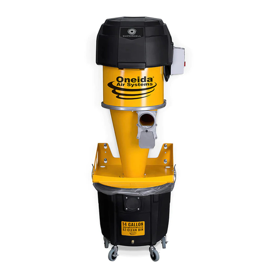
- Page 1 OWNER’S MANUAL Supercell ® High-Pressure Dust Collector 14 Gallon # XSK000014 Appearance may vary slightly Rev: 07/20/2020 Doc. #ZBM000037...
-
Page 3: Table Of Contents
Table of Contents System Start-Up Information System Speci cations System Dimensions System Contents Assembly Instructions Maintenance Troubleshooting F.A.Q. Recommended Accessories Warranty Information Notes oneida-air.com... -
Page 4: System Start-Up Information
1,500 cfm (cubic feet per minute). is exempts some small operators from the NFPA code 664, but other codes may apply in your jurisdiction. Consult Oneida Air Systems, Inc. - Page 5 System Start-Up Information (Continued) your local Fire Marshal for help. Additional information can be found in NFPA Code Book 664. e customer assumes the responsibility for contacting their insurance underwriter regarding speci c application requirements of explosion venting or if additional re protection and safety equipment may be required. 5.
-
Page 6: System Speci Cations
Cold Rolled Steel, Static Dissipative Polyethylene Inlet 4" O.D. Discharge to Drum 5" O.D. Overall Height 14 Gallon: 61" Overall Weight 14 Gallon: 76 lbs e Supercell requires a 20 Amp outlet receptacle to be installed by a licensed electrician. Oneida Air Systems, Inc. -
Page 7: System Dimensions
System Dimensions Nominal dimensions shown. Dimensions subject to slight variations in manufacturing. Mounting dimensions allow for 13/16" clearance when removing and emptying the drum Allow for an additional 24" of clearance above the Motor Assembly to allow for its removal during lter replacement and other maintenance. -
Page 8: System Contents
10-32 1/2" Phillips Pan Head Screws AFT901032 10-32 Nylock Nut Please unpack the parts carefully and con rm you have received each item listed here. * Some components are pre-installed at the factory and are listed here for your convenience. Oneida Air Systems, Inc. - Page 9 FINISH: NAME: 14Ga Galv THE INFORMATION CONTAINED IN THIS FPX040001 - Filter Hold Down 14ga rev 3 DRAWING IS THE SOLE PROPERTY OF Oneida Air Systems Inc. AND SHALL SIZE TOL: PART NO. FPX040001 NOT BE USED OR DISCLOSED TO...
-
Page 10: Assembly Instructions
(G23) and adhere them to the Wall Bracket (F), lining them up with your reference line [FIG. 1e]. Note: Press each gasket piece rmly onto the FIG. 1e bracket to ensure a long-lasting, airtight seal. Oneida Air Systems, Inc. - Page 11 Assembly Instructions (Continued) Align the Latches (G14) onto the holes on either side of the Wall Bracket (F) and secure them in place using two Pan-Head Screws (G15) and Nylock Nuts (G16) [FIG 2]. Note: Firmly tighten this hardware. You may need to open the latch to access the screw holes for mounting.
- Page 12 Place washers onto each fastener and thread 1/2" 13 mm the fasteners into all four holes, leaving at least 1/2" outside of the hole to t the Wall Bracket (F) and Rear Support Brace (G13) [FIG. 7]. FIG. 7 Oneida Air Systems, Inc.
- Page 13 Assembly Instructions (Continued) Li the Wall Bracket (F) up and over the fasteners so that the washer is on the inside of the bracket. Slide the Wall Bracket (F) down so that the fastener is snugly inside the smaller section of each keyhole [FIG. 8]. FIG.
- Page 14 Rubber Washer (G9), and Whiz-Lock Nut (G10) as shown in [FIG. 13]. Note: Ensure that the Whiz-Lock Nuts are torqued down so that the rubber washers are rmly compressed - this will prevent air leaks. FIG. 13 Oneida Air Systems, Inc.
- Page 15 Assembly Instructions (Continued) Install the three remaining Hex Head Bolts (G7), Flat Washers (G8), Rubber Washers (G9), and Whiz-Lock Nuts (G10) to the three remaining holes in the Cyclone’s (E) upper ange [FIG. 14]. Note: Ensure that the Whiz-Lock Nuts are torqued down so that the rubber washers are rmly compressed - this will prevent air leaks.
- Page 16 (by roughly 50%). FIG. 17 Open and slide the Ring Clamp (D) over the assembly so that it rests outside the upper ange of the Cyclone (E) [FIG. 18]. FIG. 18 Oneida Air Systems, Inc.
- Page 17 Assembly Instructions (Continued) Install the Barrel Gasket (G2) onto the rounded, bottom edge of the Motor Assembly (A). e Barrel Gasket (G2) should be oriented so that the "ribbed" side is facing downwards [FIG. 19]. FIG. 19 Attach one end of the Vinyl Tubing (G18) onto the hose tting located underneath the Motor Assembly's (A) plastic cowl.
- Page 18 Note: Which hole you use will be determined by the orientation of your Motor Assembly (A). Use whichever hole is closest to ensure adequate length for the Vinyl Tubing (G18) to connect to the Drum (J1). FIG. 23 Oneida Air Systems, Inc.
- Page 19 Assembly Instructions (Continued) Connect the Dust Sentry's power adapter (I) to the small cord next to the Motor Assembly's (A) magnetic starter [FIG. 24]. e Dust Sentry's strobe light (I) should be mounted in a highly visible area using adhesive strips or the two mounting holes.
- Page 20 Drum (J1) [FIG. 29]. Note: If you do not wish to use a liner bag you must insert Round Tapered Plug (G19G) into the Quick Disconnect Kit (G19) from inside the Drum (J1). FIG. 29 Oneida Air Systems, Inc.
- Page 21 Assembly Instructions (Continued) Attach the other end of the Vinyl Tubing (G18) onto the Nylon Elbow (G19A) installed on the lower section of the Drum (J1). Push the tubing onto the elbow so that all the barbs are covered [FIG. 30]. G19A FIG.
-
Page 22: Maintenance
3. Unlatch the Ring Clamp (D) at the base of the motor section and allow it to hang freely. Remove the motor section and set aside. 8. Replace the motor section and re-latch the drum clamp around the motor section. Oneida Air Systems, Inc. - Page 23 Maintenance (Continued) Emptying the Drum Cleaning out the Cyclone When rst using the dust collector, check the Drum If the drum becomes over lled and the cone is Window (J1) regularly to get an idea of how o en packed with dust: it needs to be emptied.
- Page 24 4. Remove the plenum plate and set aside (there is no against the bottom of the motor. hardware securing the plenum plate, it is compressed between the cowling and the motors). Oneida Air Systems, Inc.
- Page 25 Maintenance (Continued) 9. Place motors back on the motor plate. Replace the motor 11. Re-secure the motor hold down plate using the ve 5/16- hold down plate, ensure wires sit above the plate, ensure 18" Nylock Nuts. Note: DO NOT OVERTIGHTEN. Install the provided the tabs on the motors line up with the notches on the hold down plate.
-
Page 26: Troubleshooting
2. Review the Maintenance section on how to replace the motor. If you continue to experience difficulty with your dust collector, call Oneida Air Systems’ Customer Service Department at 1-866-387-8822 or email support@oneida-air.com. Oneida Air Systems, Inc. -
Page 27: F.a.q
What dust can be collected? Oneida Air Systems' dust collectors are designed and tested for wood and wood dust. ey can and have been used e ectively for various other dusts and chips, such as drywall dust, paper dust, agricultural dust, metal chips and other forms of debris. -
Page 28: Recommended Accessories
• Turn your dust collector into vacuum system with this complete hose accessory kit. • Crush-resistant hose features smooth inner wall for minimal air resistance. • Includes common vacuum head accessories including crevice tool, oor tool, and more! Oneida Air Systems, Inc. - Page 29 Recommended Accessories (Continued) 5" Hose Quick Connect Adapter Kit #DQK050000 • Simplify 5" ex-hose connections to your tools and dust collection systems/ductwork. • Made from heavy-gauge, galvanized steel. • Includes both the male (crimped) and female (non-crimped) Hose Quick Connect ttings. 4"...
-
Page 30: Warranty Information
Oneida Air Systems makes every e ort to accurately represent our products and prices, however Oneida Air Systems reserves the right to make changes to products and prices at any time. As a manufacturer, Oneida Air Systems reserves the right to change product speci cations at any time in an e ort to achieve better quality products. -
Page 31: Notes
Notes oneida-air.com... - Page 32 Regardless of where you purchased your system, if you have any questions or issues with missing / damaged parts, please call Oneida Air Systems rst to let us help resolve your problem. We fully stand behind the quality of our product and place the utmost value satisfaction of our customers.
Need help?
Do you have a question about the Supercell XSK000014 and is the answer not in the manual?
Questions and answers