Table of Contents
Advertisement
Quick Links
Advertisement
Table of Contents

Related Manuals for Smartgen HAT163


Summary of Contents for Smartgen HAT163
- Page 1 HAT163 ATS CONTROLLER USER MANUAL SMARTGEN (ZHENGZHOU) TECHNOLOGY CO.,LTD.
- Page 2 SmartGen Technology at the address above. Any reference to trademarked product names used within this publication is owned by their respective companies. SmartGen Technology reserves the right to change the contents of this document without prior notice. Table 1 - Software Version Date...
-
Page 3: Table Of Contents
HAT163 ATS CONTROLLER USER MANUAL CONTENTS OVERVIEW ............................4 PERFORMANCE AND CHARACTERISTICS ..................4 SPECIFICATION ..........................5 OPERATION ............................6 4.1 FRONT PANEL DESCRIPTION ......................6 4.2 KEY FUNCTION DESCRIPTION......................6 4.3 INDICATOR DESCRIPTION ....................... 7 4.4 OPERATION ............................7 4.4.1... -
Page 4: Overview
1 failure, controller will send signal to start the genset. Moreover, it can also realize remote communication, remote control and parameter configuration functions via LINK port communication. 2. PERFORMANCE AND CHARACTERISTICS HAT163 controller can detect 2-way voltage (2-way mains, 1-way mains and 1-way gen ) and control ATS. Mains characters are as below, ─... -
Page 5: Specification
HAT163 ATS CONTROLLER USER MANUAL 3. SPECIFICATION Table 2 – Specification Parameters Items Contents AC power A1N1/A2N2 supply. Operating Voltage Rated 240VAC (range: AC170V~AC277V) Power Consumption Under rated voltage, power consumption is not more than 3VA AC Voltage Input: AC170V – AC277V (ph-N) 3-phase 4-wire AC170V –... -
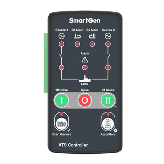
Page 6: Operation
HAT163 ATS CONTROLLER USER MANUAL 4. OPERATION 4.1 FRONT PANEL DESCRIPTION Fig.1 – Front Panel Description KEY FUNCTION DESCRIPTION Table 3 – Keys Description Icon Function Description Auto/Manual mode switch; Auto (Set) Enter into lamp test status by pressing for 3s;... -
Page 7: Indicator Description
HAT163 ATS CONTROLLER USER MANUAL INDICATOR DESCRIPTION Tale 4 – Indicator Description Indicators Description Lamp illuminates: 1# power normal Lamp flashes: 1# power abnormal (over/under voltage, over/under 1# Power frequency, loss of phase, and phase rotation) Lamp off: 1# loss of power... -
Page 8: Auto Operation
HAT163 ATS CONTROLLER USER MANUAL 4.4.3 AUTO OPERATION In auto mode, controller can switch between 1# supply and 2# supply automatically. 4.4.4 MANUAL TEST In manual mode, when genset start signal is active, press can deactivate the genset start signal. - Page 9 HAT163 ATS CONTROLLER USER MANUAL Items Function Description Remark 2-phase 3-wire: connect with A1, B1, and N1; C1 is not connected; 3-phase 3-wire: connect with A1, B1, and C1; N1 is not connected (special order required). Gen Start Volt free normally close...
-
Page 10: Definition And Range Of Parameters
HAT163 ATS CONTROLLER USER MANUAL 7. DEFINITION AND RANGE OF PARAMETERS Table 6 – Parameters Definition and Range Table (1) Items Range Default Description 1: 3 Phase, 4 Wire (3P4W) 2: Single Phase, 2 Wire (1P2W) AC System (1-4) 3: 3 Phase, 3 Wire (3P3W) (special order required) - Page 11 HAT163 ATS CONTROLLER USER MANUAL Items Range Default Description 1: 1s 2: 3s 3: 5s Breaker Switch (1-7) 4: 8s Interval 5: 10s 6: 15s 7: User defined(Default: 1s) 1: 0.5s 2: 1s 3: 2s Transfer Delay (1-7) 4: 3s...
- Page 12 HAT163 ATS CONTROLLER USER MANUAL Item Range Default Description 0: Disabled Over Frequency Warn (0-1) 1: Enabled Over Frequency Set (100-120)% Threshold value Value Over Frequency (100-120)% Return value Return Value Under Frequency 0: Disabled (0-1) Warn 1: Enabled Under Frequency Set...
-
Page 13: Parameters Setting
HAT163 ATS CONTROLLER USER MANUAL 8. PARAMETERS SETTING 8.1 PARAMETERS SETTING MODE In manual mode, enter into parameters setting mode by pressing for 8s and manual/auto flash; ①, ②, ③, ④ indicators illuminate. LED numbers please to indicator and gen status indicator see the following picture. -
Page 14: Reset To Default
HAT163 ATS CONTROLLER USER MANUAL Table 8 – Parameter Value Comparison Parameter Serial No. LED Indicate Parameter Value LED Indicate Value Value ① ② ③ ④ ⑤ ⑥ ⑦ 8.3 RESET TO DEFAULT , ①, ② and ③ LEDs illuminated, and ⑦ LED flashes. -
Page 15: Typical Application
HAT163 ATS CONTROLLER USER MANUAL 9. TYPICAL APPLICATION Fig.4 – ATyS d M Application Drawing HAT163 ATS Controller 2018-05-20 Version 1.0 Page 15 of 21... - Page 16 HAT163 ATS CONTROLLER USER MANUAL Fig.5 – ATyS d Application Drawing HAT163 ATS Controller 2018-05-20 Version 1.0 Page 16 of 21...
- Page 17 HAT163 ATS CONTROLLER USER MANUAL Fig.6 – VITZRO/FEITENG ATS Apllication Drawing NOTE: Please conference the above drawings for wiring. The actual wiring on site is subject to the ATS switch wiring instructions. And the capacity of the fuse should be selected according to the actual power consumption at the site, which cannot be based on the fuse capacity in the drawing.
- Page 18 HAT163 ATS CONTROLLER USER MANUAL Fig.7 – LO/NO Output Internal Wiring Connection NOTE: F1 and F2 specification is 10A/250VAC, if using LO/NO as ATS’s power supply, the max. circuit current of ATS is 10A. Fig.8 – 2 Phase 3 Wire Connection Fig.9 –...
-
Page 19: Overall Dimension And Panel Cutout
HAT163 ATS CONTROLLER USER MANUAL 10. OVERALL DIMENSION AND PANEL CUTOUT 10.1 CASE DIMENSION Unit: mm Fig.10 – Overall Dimensions 10.2 CUTOUT The controller has three installation ways: panel built-in, internal 35mm slideway and internal screw mounting. Panel built-in and internal screw mounting are as below: Fig.11 –... -
Page 20: Installation
HAT163 ATS CONTROLLER USER MANUAL 10.3 INSTALLATION Fig. 12 – Panel Built-in Installation Fig.13 – 35mm Sideway Installation Fig.14 – Internal Screw Installation HAT163 ATS Controller 2018-05-20 Version 1.0 Page 20 of 21... -
Page 21: Trobleshooting
HAT163 ATS CONTROLLER USER MANUAL 11. TROBLESHOOTING Tale 9 - Troubleshooting Symptom Possible Solutions Check connections and voltages of 1# and 2# power; Controller inoperative Check F1 or F2 fuse Controller displays normal Check ATS; but switch not activate Check the connections between controller and ATS.
Need help?
Do you have a question about the HAT163 and is the answer not in the manual?
Questions and answers