
Related Manuals for Smartgen HAT530P Series


Summary of Contents for Smartgen HAT530P Series
- Page 1 HAT530P/HAT530PC SERIES ATS CONTROLLER USER MANUAL SMARTGEN (ZHENGZHOU) TECHNOLOGY CO., LTD.
- Page 2 SmartGen Technology at the address above. Any reference to trademarked product names used within this publication is owned by their respective companies. SmartGen Technology reserves the right to change the contents of this document without prior notice. Table 1 - Software Version Date...
-
Page 3: Table Of Contents
CONTENT OVERVIEW ..............................4 PERFORMANCE AND CHARACTERISTICS ....................4 SPECIFICATION ............................5 PANEL INSTRUCTION ..........................6 OPERATION PANEL ........................6 INDICATORS DESCRIPTION......................6 PARAMETER SETTING OF PANEL OPERATION ..................7 PANEL OPERATION SETTING ...................... 7 MASTER SETTING ......................... 7 AC SYSTEM SETTING ........................8 DELAY ADJUSTMENT ........................ -
Page 4: Overview
1 OVERVIEW HAT530P/HAT530PC series dual power ATS controller consists of microprocessor as the core, can precisely detect voltage (2-way 3-phase/single phase), make accurate judgement on abnormal voltage (power lost, over/under voltage, over/under frequency, loss of phase, reverse phase sequence) and control ATS to transfer after the delay has expired. The controller is applicable for two-stage ATS and three-stage ATS with controlling the start of genset. -
Page 5: Specification
3 SPECIFICATION Table 2 – Product Specification Items Contents Operating Voltage AC supply L1N1/L2N2, voltage range AC (170~277)V. Power Consumption <3W (Standby mode: <1W) AC Voltage Input 3P4W AC170V~AC277V(ph-N) 1P2W AC170V~AC277V (ph-N) 2P3W AC170V~AC277V(ph-N) 3P3W AC170V~AC277V(ph-ph) (Refer to 3P3W wiring diagram) Rated Frequency 50/60Hz S1 Close Relay Output... -
Page 6: Panel Instruction
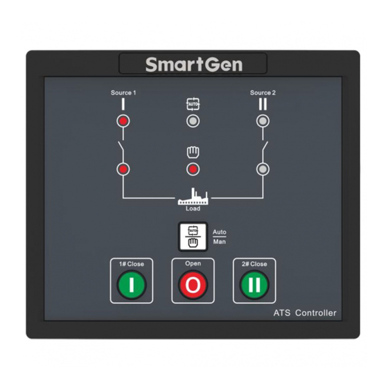
4 PANEL INSTRUCTION 4.1 OPERATION PANEL Fig.1 – Panel Drawing 4.2 INDICATORS DESCRIPTION Table 3 – Indicator Function Description in Normal Testing Mode Items Description It is illuminated when S1 power is normal; flashing when S1 power state is S1 Power Indicator abnormal;... -
Page 7: Parameter Setting Of Panel Operation
5 PARAMETER SETTING OF PANEL OPERATION 5.1 PANEL OPERATION SETTING Pressing and holding the button for more than 3s, all LEDs are illuminated to enter into lamp test mode; Pressing and holding the button for more than 7s, all LEDs are flashing (500ms per time) to enter into parameter setting status, and release button;... -
Page 8: Ac System Setting
5.3 AC SYSTEM SETTING Firstly, make controller enter parameter setting status and then conduct the setting. Procedures of setting “Single-phase 2-wire”, “3-phase 4-wire”, “2-phase 3-wire” and “3-phase 3-wire”: Press at the same time, when S1/S2 power indicator and auto indicator are illuminated;... -
Page 9: Factory Reset Delay Value
After adjusting the delays, press . When S1/S2 power indicator and automatic indicator are illuminated simultaneously, the adjusted values has been saved. The controller will go back to normal status automatically after all LEDs are flashing 5 times rapidly and controller will work according to the set delay values. -
Page 10: Parameter Configeration
6 PARAMETER CONFIGERATION 6.1 PARAMETERS TABLE Table 4 – Parameters Setting Table Item Range Default Description Can be set via It is the delay of #1 power from voltage 1# Normal Delay (0-60)s controller abnormal to voltage normal. Generally, it potentiometer is 10s. - Page 11 (0-1) 1: 2 stop bits. NOTE 1: Parameters above are configured via PC software of SmartGen. The PC programming connection is to use RS485 interface of SG72 module connecting with RS485 interface of controller. NOTE 2: “1# Voltage Normal Delay” and “2# Voltage Normal Delay” can be set only via the potentiometer which locates nearby the back panel terminal.
-
Page 12: Operation Control
7 OPERATION CONTROL When controller is running, pressing key can set the controller as Auto mode or Manual mode (indicated by automatic and manual indicators). In Auto mode, controller can automatically transfer the load to S1 or S2 power. When it is set to Auto Trans. Auto Restore, master power is normal, and controller will transfer to master power end in priority. - Page 13 Table 5 - Terminal Function Table Terminal No. Item Description Remark 1# AC 3P4W voltage If it is single phase input, only input connect with A1, N1. 2# AC 3P4W voltage If it is single phase input, only input connect with A2, N2. ATS power supply N Provide power supply for ATS.
-
Page 14: Rs485 Connection
8.2 RS485 CONNECTION The connection between RS485 and adaptor is shown below: Fig. 3 – RS485 Connection Diagram 9 ATS POWER SUPPLY The controller has built-in ATS power supply automatic switching function. If the voltage between S1and S2 is normal, this can ensure ATS power supply normally by transferring between N/O contact output and N/C contact output of the intermediate relay 1/2. -
Page 15: Typical Wiring Diagram
10 TYPICAL WIRING DIAGRAM Fig. 5 - SGQ-N/T Application Diagram Fig. 6 – FEITENG Application Diagram HAT530P/HAT530PC Series ATS Controller User Manual Page 15 of 18... - Page 16 Fig. 7 - ATyS d Application Diagram Fig. 8 –Three–stage Application Diagram of Motor Type NOTE: 1. The diagram is for reference only. The actual wiring shall follow the ATS instruction. Users should choose proper fuse capacity according to the actual power consumption. HAT530P/HAT530PC Series ATS Controller User Manual Page 16 of 18...
- Page 17 NOTE:The 3P3W wiring diagram shown in the picture above is the AC 220V line voltage. If the actual application is different from it, please contact with SmartGen’s technical staff to get the specific wiring methods. HAT530P/HAT530PC Series ATS Controller User Manual...
-
Page 18: Installation
11 INSTALLATION Unit: mm Fig. 12 - Installation Dimensions _________________________________ HAT530P/HAT530PC Series ATS Controller User Manual Page 18 of 18...
Need help?
Do you have a question about the HAT530P Series and is the answer not in the manual?
Questions and answers