Table of Contents
Advertisement
Quick Links
Advertisement
Table of Contents

Related Manuals for Smartgen HAT530N


Summary of Contents for Smartgen HAT530N
- Page 1 HAT530N ATS CONTROLLER USER MANUAL...
- Page 2 Smartgen Technology at the address above. Any reference to trademarked product names used within this publication is owned by their respective companies. SmartGen Technology reserves the right to change the contents of this document without prior notice. Table 1 - Software Version Date...
-
Page 3: Table Of Contents
DESCRIPTION OF CONNECTING TERMINALS .................. 13 BACK PANEL ............................13 FUNCTION DESCRIPTION OF WIRING TERMINALS ..............14 ATS POWER SUPPLY ........................15 TYPICAL WIRING DIAGRAM ......................16 INSTALLATION ..........................18 FAULT FINDING ..........................19 HAT530N ATS CONTROLLER Page 3 of 19... -
Page 4: Overview
1 OVERVIEW The powerful Microprocessor contained within the HAT530N ATS controller allows for precision voltage (2-way 3-phase/single phase) measuring and make accurate judgment on abnormal voltage (power lost, over/under voltage, over/under frequency, loss of phase, phase sequence wrong) and control ATS to transfer after the delay has expired. This controller is suitable for NO Breaking ATS and ONE Breaking ATS. -
Page 5: Specification
IP65 Gasket: when waterproof gasket is installed between controller and Protection Level control window. Apply AC1.5kV voltage between high voltage terminal and low voltage Insulation Strength terminal and the leakage current is not more than 3mA within 1min. Weight 0.51kg HAT530N ATS CONTROLLER Page 5 of 19... -
Page 6: Operating
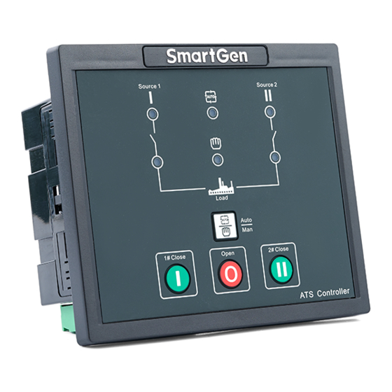
4 OPERATING 4.1 OPERATION PANEL Fig.1 – HAT530N Panel Drawing 4.2 INDICATORS DESCRIPTION Table 3 – Indicator Function Description in Normal Testing Mode Items Description It is illuminated when 1# power is normal; flashing when 1# power state is 1# Power Indicator abnormal;... -
Page 7: Panel Operation For Parametter Setting
Go back to the current parameter No. to check the status; If the parameter is set to the last No.6 of delay adjustment, press button to select the item, press button to adjust the number, the indicator of setting items flashes once, HAT530N ATS CONTROLLER Page 7 of 19... - Page 8 Note 1: Each time the controller is power on, the main use status of the controller can be judged by the following three conditions. If the 1# power indicator flashes 3 times rapidly, the #1 power is main use. HAT530N ATS CONTROLLER Page 8 of 19...
- Page 9 Note 7: When parameter is set to restore the factory default setting and delay adjustment, press button and press button again; when the indicator of setting item No. flashes, press button to save the configuration. HAT530N ATS CONTROLLER Page 9 of 19...
-
Page 10: Parameter Configeration
(0-1) 0: Disable;1: Enable Voltage upper limit; it is abnormal when the Over Voltage (100-120)% voltage has exceed the set value. Over Volt Return (100-120)% Voltage upper limit return value; it is normal HAT530N ATS CONTROLLER Page 10 of 19... - Page 11 (0-23) OUTPUT FUNCTION DESCRIPTION NOTE1: Parameters above are configured via PC software of SmartGen. The PC programming connection is to use LINK interface of SG72 module connecting with LINK interface of controller. NOTE2: “1# Normal Delay” and “2# Normal Delay” can be set only via the potentiometer which locates nearby the back panel terminal.
-
Page 12: Output Function Description
Each Backup, controller will not detect Auto Trans. Auto Restore setting. In Manual mode, press key, load will be transferred to 1# power supply; press to disconnect load supply; press key, load will be transferred to 2# power supply. HAT530N ATS CONTROLLER Page 12 of 19... -
Page 13: Description Of Connecting Terminals
8 DESCRIPTION OF CONNECTING TERMINALS 8.1 BACK PANEL Fig. 3 – HAT530N Rare Panel Drawing HAT530N ATS CONTROLLER Page 13 of 19... -
Page 14: Function Description Of Wiring Terminals
When active, the ATS is in Neutral Force Open Connect COM2 is active. Position. COM Port Input COM COM2 2# AC 3-phase 4 wire voltage For single phase, only connect A2, input Communication Communicate with PC/Program LINK Port update HAT530N ATS CONTROLLER Page 14 of 19... -
Page 15: Ats Power Supply
Output 1 and Auxiliary Output 2 should be set as “Not used”. If the Auxiliary output 1 and Auxiliary Output 2 are used for something function other than the “ATS Power Supply”, corresponding function items should be set. HAT530N ATS CONTROLLER Page 15 of 19... -
Page 16: Typical Wiring Diagram
10 TYPICAL WIRING DIAGRAM Fig. 6 - ATySM3s Wiring Diagram Fig. 7 - ATyS3s Wiring Diagram HAT530N ATS CONTROLLER Page 16 of 19... - Page 17 NOTE: The diagram is for reference only. The actual wiring shall follow the ATS instruction. Users should choose proper fuse capacity according to the actual power consumption. If SOCOMEC VS is applied, the Close delay and Open delay must be no less than 5s (Default: 5s). HAT530N ATS CONTROLLER Page 17 of 19...
-
Page 18: Installation
Fig. 11 - Single phase 2-wire Wiring Diagram NOTE:Above pictures take the AC 220V voltage as example. If AC 110V voltage is applied in actual use, please contact with SmartGen technical staff to get the specific wiring methods. 11 INSTALLATION Fig. -
Page 19: Fault Finding
Check the connection wirings between the controller and the ATS. Electrical parameters detection Check controller wring; error Modify electrical parameters detection value. PC software communication failure Check communication port setting and connections. _________________________________ HAT530N ATS CONTROLLER Page 19 of 19...
Need help?
Do you have a question about the HAT530N and is the answer not in the manual?
Questions and answers