Table of Contents
Advertisement
Quick Links
Advertisement
Table of Contents

Related Manuals for Smartgen HAT530


Summary of Contents for Smartgen HAT530
- Page 1 HAT530 ATS CONTROLLER USER MANUAL Smartgen Technology...
- Page 2 (including photocopying or storing in any medium by electronic means or other) without the written permission of the copyright holder. Smartgen Technology reserves the right to change the contents of this document without prior notice. If colors of actual products are different from those mentioned within this manual, please...
- Page 3 Software Version Version Date Note 2014-06-23 Original release. Clarification of notation used within this publication. SIGN INSTRUCTION Highlights an essential element of a procedure to ensure correctness. NOTE...
-
Page 4: Table Of Contents
HAT530 ATS CONTROLLER CONTENT OVERVIEW ........................5 PERFORMANCE AND CHARACTERISTICS ............... 6 SPECIFICATION ......................8 OPERATING ......................... 9 PANEL BUTTON OPERATION ................... 10 PRIORITY SETTING ......................... 11 AC SYSTEM SETTING........................12 DELAY ADJUSTMENT ........................13 RESTORE FACTORY DEFAULT ...................... 14 PROGRAMMED PARAMETER AND RANGE ............. -
Page 5: Overview
HAT530 ATS CONTROLLER 1 OVERVIEW The powerful Microprocessor contained within the HAT530 ATS controller allows for precision voltage (2-way 3-phase/single phase) measuring and make accurate judgment on abnormal voltage (power lost, over/under voltage, over/under frequency, loss of phase, phase sequence wrong) and control ATS to transfer after the delay has expired. This controller is suitable for NO Breaking ATS and ONE Breaking ATS. -
Page 6: Performance And Characteristics
HAT530 ATS CONTROLLER 2 PERFORMANCE AND CHARACTERISTICS HAT530 ATS controller can monitor 2-way 3-phase 4-wire voltage, 2-phase 3-wire and single-phase 2-wire voltage (2 way mains, or 1 way mains and 1 way generator) and control ATS to transfer. Its performance and characteristics are shown as below, ◙... - Page 7 HAT530 ATS CONTROLLER DC28V, passive N/C contact. ◙ Suitable for various AC systems (3 phase 4-wires, 2-phase 3-wires and single-phase 2-wire). ◙ Controller has strong ability of anti-electromagnetic interference, can be used under complex electromagnetic interference environment. ◙ Modular design, self extinguishing ABS plastic shell, pluggable terminal, built-in mounting,compact structure with easy installation.
-
Page 8: Specification
HAT530 ATS CONTROLLER 3 SPECIFICATION Items Contents Operating Voltage AC170V~277V during AC power L1N1/L2N2 supply. Power Consumption <3W (Standby mode: <1W) AC Voltage Input AC170V~AC277V(ph-N) 3P4W (ph-N) AC170V~AC277V (ph-N) 1P2W (ph-N) AC170V~AC277V(ph-N) 2P3W (ph-N) Rated Frequency 50/60Hz 1# Close Relay Output... -
Page 9: Operating
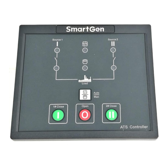
HAT530 ATS CONTROLLER 4 OPERATING NOTE: indicators description: 1. Indicators Description (in test mode): 1# Power Indicator:It is illuminated when 1# power is normal; flashing when 1# power state is abnormal; off when there is no 1# power. 2# Power Indicator:It is illuminated when 2# power is normal; flashing when 2# power state is abnormal;... -
Page 10: Panel Button Operation
HAT530 ATS CONTROLLER 5 PANEL BUTTON OPERATION Pressing and holding the button for more than 3s, all LEDs are illuminated to enter into lamp test mode; under this mode, the controller will back to normal status automatically after release the button. -
Page 11: Priority Setting
HAT530 ATS CONTROLLER 5.1 PRIORITY SETTING Power priority can be set only when the controller is in parameters setting status. Procedures of setting “1# power priority”, “2# power priority” and “No priority”: 1) Press at the same time, when 1#/2# power indicator and auto indicator are illuminated;... -
Page 12: Ac System Setting
HAT530 ATS CONTROLLER 5.2 AC SYSTEM SETTING AC system can be set only when the controller is in parameters setting status. Procedures of setting “Single-phase 2-wire”,“3-phase 4-wire” and “2-phase 3-wire”: 1) Press at the same time, when 1#/2# power indicator and auto indicator are illuminated;... -
Page 13: Delay Adjustment
HAT530 ATS CONTROLLER 5.3 DELAY ADJUSTMENT Delay value can be set only when the controller is in parameters setting status. ♦ Adjusting “1# normal” potentiometer (locate nearby the back panel terminal) can set output delay after 1# power supply is normal. -
Page 14: Restore Factory Default
HAT530 ATS CONTROLLER 5.4 RESTORE FACTORY DEFAULT Default value can be set only when the controller is in parameters setting status. a) Press at the same time, when 1#/2# power indicator and auto indicator are illuminated; release the two buttons, then the auto indicator and 1#/2# power indicators are extinguished simultaneously which means the default delay value of the controller can be set. -
Page 15: Programmed Parameter And Range
HAT530 ATS CONTROLLER 6 PROGRAMMED PARAMETER AND RANGE 6.1 PARAMETERS TABLE Item Range Default Description Can be set It is the delay of #1 power from Normal (0-60)s via controller voltage abnormal voltage Delay potentiometer normal. Generally, it is 10s. - Page 16 HAT530 ATS CONTROLLER Item Range Default Description Over Voltage upper limit return value; it Voltage (100-120)% is normal only when the voltage Return fallen below the set value. Voltage lower limit; it is abnormal Under (70-100)% when the voltage has fallen below voltage the set value.
- Page 17 HAT530 ATS CONTROLLER Item Range Default Description DESCRIPTION NOTE: “1# Normal Delay” and “2# Normal Delay” can be set only via the potentiometer which locate nearby the back panel terminal. “1# Abnormal Delay” and “2# Abnormal Delay” can be set via the PC software or potentiometer which locate nearby the back panel terminal.
-
Page 18: Input/Output Function Description
HAT530 ATS CONTROLLER 6.2 OUTPUT FUNCTION DESCRIPTION The output port function as below, Items Description 00. Not used Invalid. 01. 1# Normal volt It will output when1# voltage is normal. 02. 1# Abnormal volt It will output when 1# voltage is abnormal. -
Page 19: Operation Control
HAT530 ATS CONTROLLER 7 OPERATION CONTROL Auto/Manual operation: When controller is running, pressing key can set the controller as Auto mode or Manual mode (indicate by automatic and manual indicators). In Manual mode, press key, load will be transferred to 1# power supply; press key, load will be transferred to 2# power supply. -
Page 20: Description Of Connecting Terminals
HAT530 ATS CONTROLLER 8 DESCRIPTION OF CONNECTING TERMINALS Terminal description: Items Description Remark Default: ATS Power A Volt-free relay contact output; Aux. Output 1 Phase Rated 16A. Default: ATS Power N Volt-free relay contact output; Aux. Output 2 Phase Rated 16A. - Page 21 HAT530 ATS CONTROLLER Items Description Remark Detection of 1# ATS closing 1# Close Input Connect COM2 is active. status; auxiliary contact input Detection of 2# ATS closing 2# Close Input Connect COM2 is active. status; auxiliary contact input When active, the ATS is in Force Open Connect COM2 is active.
-
Page 22: Ats Power Supply
HAT530 ATS CONTROLLER 9 ATS POWER SUPPLY The power of ATS is supplied by controller, as long as one power is normal, this can ensure ATS power supply normally and can be transferred properly. Users should select power supply voltage (phase voltage or line voltage) based on ATS type. -
Page 23: Typical Wiring Diagram
HAT530 ATS CONTROLLER 10 TYPICAL WIRING DIAGRAM iring Diagram ATySM3s W ring Diagram ATyS3s Wi HAT530 ATS CONTROLLER 2014-06-23 Version 1.0 Page 23 of 26... - Page 24 2-phase 3-wire Wiring Diagram Single phase 2-wire Wiring Diagram NOTE:Above pictures take the AC 220V voltage as example. If AC 110V voltage is applied in actual use, please contact with Smartgen technical staff to get the specific wiring methods. HAT530 ATS CONTROLLER 2014-06-23 Version 1.0...
-
Page 25: Installation
HAT530 ATS CONTROLLER 11 INSTALLATION HAT530 ATS CONTROLLER 2014-06-23 Version 1.0 Page 25 of 26... -
Page 26: Fault Finding
HAT530 ATS CONTROLLER 12 FAULT FINDING Symptom Possible Solutions Controller no response with Check controller wring. power. Check ATS; Genset running while ATS Check the connection wirings between the controller and the not transfer ATS. Electrical parameters Check controller wring;...
Need help?
Do you have a question about the HAT530 and is the answer not in the manual?
Questions and answers