Table of Contents
Advertisement
Quick Links
Advertisement
Table of Contents

Subscribe to Our Youtube Channel
Related Manuals for Insportline Omahan UB


Summary of Contents for Insportline Omahan UB
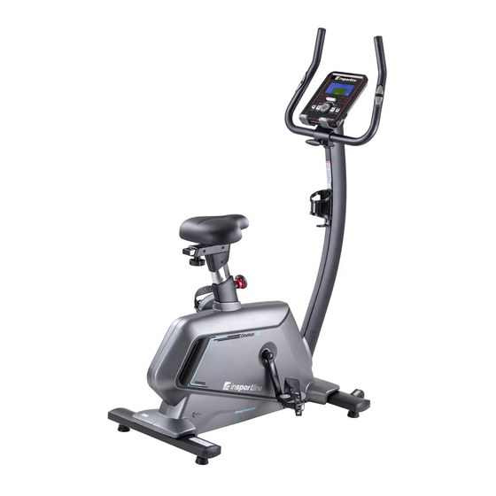
- Page 1 USER MANUAL – EN IN 20217 Exercise bike inSPORTline Omahan UB...
-
Page 2: Table Of Contents
CONTENTS SAFETY INSTRUCTIONS ........................3 IMPORTANT NOTES ..........................3 TECHNICAL SPECIFICATIONS ......................5 ASSEMBLY ............................. 6 CONSOLE ............................. 13 PROGRAMS ............................14 USE ............................... 17 EXERCISING INSTRUCTIONS ......................18 CORRECT BODY POSTURE ....................... 18 MAINTENANCE ............................ 19 STORAGE ............................. 19 IMPORTANT NOTICE ........................... -
Page 3: Safety Instructions
SAFETY INSTRUCTIONS • Read the manual carefully and keep it for future reference. • To ensure the best safety of the exerciser, regularly check it on damages and worn parts. • If you pass on this exerciser to another person or if you allow another person to use it, make sure that that person is familiar with the content and instructions in these instructions. - Page 4 • Be sure to set up the exerciser in a dry and even place and always protect it from humidity. If you wish to protect the place particularly against pressure points, contamination, etc., it is recommended to put a suitable, non-slip mat under the exerciser. •...
-
Page 5: Technical Specifications
TECHNICAL SPECIFICATIONS Model Unfolded dimension 1090 x 560 x 1490 mm Maximal load capacity 150 kg Speed ratio 10.3 External, magnetic, one directional Φ280/6,5 kg Flywheel Saddle adjustment - Vertical 10 positions, 270 mm Saddle adjustment - Horizontal 70 mm... -
Page 6: Assembly
ASSEMBLY Prepare all parts and tools in clean and free space. Follow each step carefully. - Page 7 ASSEMBLY MATERIAL Name Specification M10×70×20 Allen screw Φ 10 Flat washer Φ 10 Spring washer M4×6 Screw Spring washer M12×60 M4×16 Screw ST4×12 Screw 5×80×80S Allen key Allen key 6×66×140 t4.0×38×145 Wrench STEP 1 Attach the front stabilizer (2) to the main frame using the washer (28), spring washer (27) and bolt (26).
- Page 8 STEP 2 Attach the rear stabilizer (3) to the main frame (1) using the curved washer (28), spring washer (27) and bolt (26). STEP 3 Attach the seat post (4) to the main frame (1).
- Page 9 STEP 4 Attach the seat (5) to the seat support (60) using the nuts (59). STEP 5 Attach the seat (5) to the seat post (4) using the nut (25) and the hand screw (23). Secure the L-seat cover (16) and the R-seat cover (17) to the seat post (4) with the screws (29).
- Page 10 STEP 6 Attach the bolt (31) to the main frame (1). Connect the motor communication cable (10) and the console communication cable (9). Attach the center post (6) to the main frame (1). Remove the caps (88) first and secure with screws (31).
- Page 11 STEP 8 Connect the console communication cable (9) to the back of the console. Connect the pulse cable from the handles (11) to the console (12). Attach the bracket (8) to the middle post (6) with the screws (24). STEP 9 Attach the handle covers (14 and 15) to the center post (6) with the screws (32).
- Page 12 STEP 10 Attach the pedal L (18) and pedal R (19) to the main frame (1). STEP 11 Plug in the power.
-
Page 13: Console
CONSOLE BUTTONS START/STOP Start / stop program RESET If a program is paused or you are setting up values, returns to the menu Hold for 2 seconds, the console will restart and start user settings UP (+) Increase value MODE/ENTER Confirm settings, enter settings DOWN (-) Decrease value... -
Page 14: Programs
Pic. 3 Pic. 4 PROGRAMS MANUAL will flash in the main menu. Select the program with the UP (+) / DOWN (-) buttons and confirm with the ENTER button. Programs go in the order: MANUAL - PROGRAM - USER PROGRAM - H.R.C –... - Page 15 Press the START / STOP button to start the program. During the program, the user can use the UP (+) / DOWN (-) buttons to set the load from 1 to 16. Press the START / STOP button to pause the program. Press RESET to return to the main menu. H.R.C PROGRAM Use the UP (+) / DOWN (-) keys to select a program, select H.R.C (Pic.
- Page 16 BODY FAT PROGRAM During training, press START / STOP to stop the program and press BODY FAT (Pic. 11) to turn on the measurement. Grasp the sensors on the handles. After 8 seconds, console displays BMI, FAT% (fat percentage) Press BODY FAT again to return to the menu. E-1 (Pic.
-
Page 17: Use
Pic. 14 Pic. 15 Excellent 1,0 <F <2,0 Above average 2,0<F <2,9 Good 3,0<F <3,9 Average 4,0<F <5,9 Below the average NOTES: • Console has a 9V, 1300 mA adapter. • If the user stops pedaling for 4 minutes, the console enters Sleep mode. All data and settings are saved until next run. -
Page 18: Exercising Instructions
If you want to exercise right, you should not forget to breathe properly. Proper and regular breathing is recommended in any exercise. It is important to keep regular deep inhales and exhales. Regular and proper breathing during exercises on the exercise bike involves intense exercise of the abdominal muscles. -
Page 19: Maintenance
down the pedal. Keep your head straight with your spine to minimize the pain of the cervical muscles and upper back muscles. Always exercise fluently and rhythmically. MAINTENANCE • When assembling, tighten all screws and adjust the bike to the horizontal position. •... -
Page 20: Diagram
DIAGRAM... -
Page 21: Parts List
PARTS LIST Name Qty. Name Qty. Crank – L Main frame Crank – R Front stabilizer Rear stabilizer Strap Seat post Foam roller Motor cover – left Seat Motor cover – right Middle post Handlebars Brake cable Console Power adapter 240 V Console communication cable Magnetic sensor Motor communication cable... -
Page 22: Terms And Conditions Of Warranty, Warranty Claims
Ball-bearing 6003-2RS Screw ST4x16 One-way bearing Magnet Small pulley Screw Ball-bearing Fixed tension wheel Flywheel axis Magnet Flywheel Plastic screw ST4×12 Square cover Screw Pulse handle Hole plug ST4×20 Spring washer Screw Round end cap TERMS AND CONDITIONS OF WARRANTY, WARRANTY CLAIMS General Conditions of Warranty and Definition of Terms All Warranty Conditions stated hereunder determine Warranty Coverage and Warranty Claim Procedure. - Page 23 • Unavoidable event, natural disaster • Adjustments made by unqualified person • Improper maintenance, improper placement, damages caused by low or high temperature, water, inappropriate pressure, shocks, intentional changes in design or construction etc. Warranty Claim Procedure The Buyer is obliged to check the Goods delivered by the Seller immediately after taking the responsibility for the Goods and its damages, i.e.
Need help?
Do you have a question about the Omahan UB and is the answer not in the manual?
Questions and answers