Table of Contents
Advertisement
Quick Links
Advertisement
Table of Contents

Subscribe to Our Youtube Channel
Related Manuals for Insportline Omahan RMB


Summary of Contents for Insportline Omahan RMB
- Page 1 USER MANUAL – EN IN 20214 Recumbent inSPORTline Omahan RMB...
-
Page 2: Table Of Contents
CONTENTS SAFETY INSTRUCTIONS ........................3 IMPORTANT NOTES ..........................4 PRODUCT DESCRIPTION ........................5 TECHNICAL SPECIFICATIONS ......................5 ASSEMBLY ............................. 6 CONSOLE ............................. 14 PROGRAMS ............................15 ADVANTAGES OF RECUMBTION ....................... 18 EXERCISING INSTRUCTIONS ......................18 MAINTENANCE ............................ 19 STORAGE ............................. 19 IMPORTANT NOTICE ........................... -
Page 3: Safety Instructions
SAFETY INSTRUCTIONS • Read the manual carefully before first use and keep it for future reference. • To ensure the best safety of the exerciser, regularly check it on damages and worn parts. • If you pass on this exerciser to another person or if you allow another person to use it, make sure that that person is familiar with the content and instructions in these instructions. -
Page 4: Important Notes
IMPORTANT NOTES • Assemble the exerciser as per assembly instructions and be sure to only use the structural parts provided with the exerciser and designed for it. Prior to the assembly, make sure the contents of the delivery is complete by referring to the parts list of the assembly and operating instructions. -
Page 5: Product Description
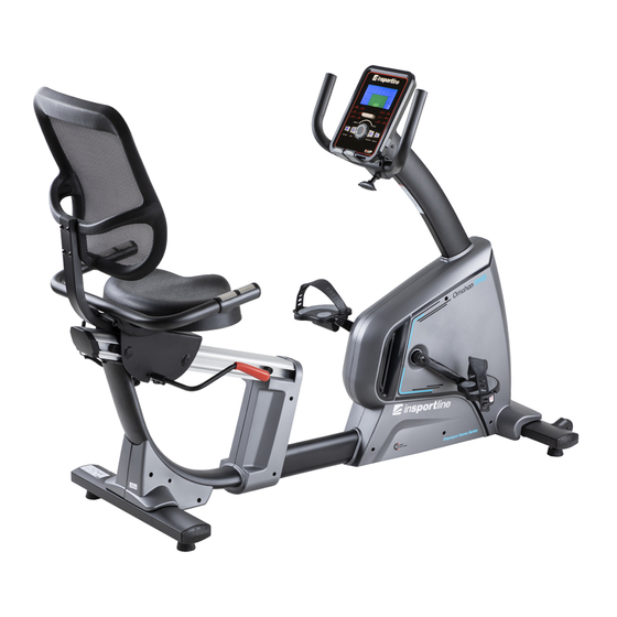
PRODUCT DESCRIPTION 1. Console 2. Middle post 3. Front stabilizer 4. Pedal 5. Rear stabilizer 6. Backrest 7. Seat 8. Pedal 9. Handlebars TECHNICAL SPECIFICATIONS Unfolded dimension 1545 x 650 x 1140 mm Maximal load capacity 120 kg Speed ratio 10.3 Load Wheel 280/9 kg... -
Page 6: Assembly
ASSEMBLY PREPARATION Name Specification M6×35 Allen screw M8×50×20 Allen screw M12×60 Allen screw M10×70×20 Allen screw M4×16 Screw ST4×12 Screw Φ8 Flat washer Φ10 Spring washer Allen screw M8x30 M6×15 Allen screw Φ10 Allen screw M6×40 Flat washer Prepare all parts and tools in clean and free space. Follow each step of the procedure carefully. - Page 8 STEP 1 Attach the front stabilizer (2) to the main frame (1) using a spring washer (36), flat washer (96) and screw (26). STEP 2 Attach the rear stabilizer (3) to the main frame (1) using a spring washer (36), flat washer (96) and bolt (26).
- Page 9 STEP 3 Connect the motor communication cable (82) to the middle post cable (83). Attach the middle post (4) to the main frame (1) with the screw (25). STEP 4 Connect the console cable (83) to the pulse cable (86). Attach the console (81) to the middle post (4) with the screw (32).
- Page 10 STEP 5 Attach the handle covers L (54) and handle covers R (55) to the middle post with screws (29). STEP 6 Attach the handles with the hand screw (65). Move the handles to a suitable position. Attach the front grip cover (56) with the screw (31).
- Page 11 STEP 7 Attach the left pedal (63) and the right pedal (64) to the main frame (1). STEP 8 Attach the seat adjustment lever (8) to the seat with the screw (21). Attach the backrest to the backrest holder with the screw (93).
- Page 12 STEP 9 Attach the seat (60) to the saddle holder with the screw (23) STEP 10 Attach the pulse sensor handles (6) to the seat with the screw (24), nut (42), and flat washer (34). Connect the pulse cables (87 and 88).
- Page 13 STEP 11 Attach the backrest (61) to the backrest bracket (11) with the screw (57). STEP 12 Plug in power.
-
Page 14: Console
CONSOLE BUTTONS START/STOP Start / stop program RESET If a program is paused or you are setting up values, returns to the menu Hold for 2 seconds, the console will restart and start user settings UP (+) Increase value MODE/ENTER Confirm settings, enter settings DOWN (-) Decrease value... -
Page 15: Programs
Pic. 3 Pic. 4 PROGRAMS MANUAL will flash in the main menu. Select the program with the UP (+) / DOWN (-) buttons and confirm with the ENTER button. Programs go in the order: MANUAL - PROGRAM - USER PROGRAM - H.R.C –... - Page 16 Press the START / STOP button to start the program. During the program, the user can use the UP (+) / DOWN (-) buttons to set the load from 1 to 16. Press the START / STOP button to pause the program. Press RESET to return to the main menu. H.R.C PROGRAM Use the UP (+) / DOWN (-) keys to select a program, select H.R.C (Pic.
- Page 17 BODY FAT PROGRAM During training, press START / STOP to stop the program and press BODY FAT (Pic. 11) to turn on the measurement. Grasp the sensors on the handles. After 8 seconds, console displays BMI, FAT% (fat percentage) Press BODY FAT again to return to the menu. E-1 (Pic.
-
Page 18: Advantages Of Recumbtion
Pic. 14 Pic. 15 Excellent 1,0 <F <2,0 Above average 2,0<F <2,9 Good 3,0<F <3,9 Average 4,0<F <5,9 Below the average NOTES: • Console has a 9V, 1300 mA adapter. • If the user stops pedaling for 4 minutes, the console enters Sleep mode. All data and settings are saved until next run. -
Page 19: Maintenance
Upper thigh Lean against a wall with one hand. Reach down and behind you. Lift up your right or left foot to your buttock as high as possible. Keep for 30 seconds and repeat twice for each leg. Hamstring stretched Sit and outstretch your right leg. -
Page 20: Environment Protection
ENVIRONMENT PROTECTION After the product lifespan expired or if the possible repairing is uneconomic, dispose it according to the local laws and environmentally friendly in the nearest scrapyard. By proper disposal you will protect the environment and natural sources. Moreover, you can help protect human health. -
Page 21: Diagram
DIAGRAM... -
Page 22: Parts List
PARTS LIST Name Qty. Name Qty. Spring washer Φ10 Main frame Circlip for shaft Φ8 Front stabilizer Circlip for shaft Φ10 Rear stabilizer Circlip for shaft Φ12 Middle post Circlip for shaft Φ17 Handlebars Allen screw M6×20 Handlebars with pulse sensor Seat post Nut M8 Seat adjustment... -
Page 23: Terms And Conditions Of Warranty, Warranty Claims
PU wheel Magnetic inductor 200 mm Power communication wire 750 Brake block Square pipe plug Power adapter Square pipe plug Spring wire 2000 mm Wire plug Pulse cable 1, 2x 100 mm Hole plug Pulse cable 2, 650 mm Brake clearance set Handle pulse Foam grip Magnet... - Page 24 Strakonická 1151/2c, Praha 5, 150 00, ČR Registered Office: Dělnická 957, Vítkov, 749 01 Headquaters: Warranty & Service: Čermenská 486, Vítkov 749 01 CRN: 26847264 VAT ID: CZ26847264 Phone: +420 556 300 970 E-mail: eshop@insportline.cz reklamace@insportline.cz servis@insportline.cz Web: www.inSPORTline.cz inSPORTline s.r.o.
- Page 25 Headquaters, warranty & service center: Električná 6471, Trenčín 911 01, SK CRN: 36311723 VAT ID: SK2020177082 Phone: +421(0)326 526 701 E-mail: objednavky@insportline.cz reklamacie@insportline.cz servis@insportline.cz Web: www.inSPORTline.sk...
Need help?
Do you have a question about the Omahan RMB and is the answer not in the manual?
Questions and answers