
Related Manuals for Hammer Strength HDW-SQST


Summary of Contents for Hammer Strength HDW-SQST
- Page 1 Heavy Duty Athletic NX Racks Owner's Manual HDW‑SQST, HDW‑HR, HDW‑PR, HDW‑HHCR, HDW‑PHCR, HDW‑PPCR 1020647-0001 REV AD...
- Page 3 Corporate Headquarters 10601 W Belmont Ave, Franklin Park, IL 60131 • U.S.A. 847.288.3300 • FAX: 847.288.3703 Service phone number: 800.351.3737 (toll-free within U.S.A., Canada) Global Website: www.lifefitness.com International Offices AMERICAS EUROPE, MIDDLE EAST, and AFRICA (EMEA) All Other EMEA Countries and Distributor Business EMEA* North America Belgium, Netherlands, and Luxemburg...
- Page 4 User and Service Documents Link https://lifefitness9512.zendesk.com/hc/en-us https://www.lftechsupport.com/web/document-library/documents Additional information is available online using the links above. أ علاه إل ر إبط باستخدإم إ لإ ن تر نت على إضافية معلومات تتوفر 点击上面的链接可在线获取更多信息。 Flere oplysninger er tilgængelige online gennem linket ovenfor. Bijkomende informatie is online beschikbaar via bovenstaande link.
-
Page 5: Table Of Contents
© Copyright 2023, Life Fitness, LLC. All Rights Reserved. Life Fitness, Hammer Strength, Cybex, ICG and SCIFIT are registered trademarks of Life Fitness, LLC and its affiliated companies and subsidiaries. Disclaimer: Images and specifications are current as of the date of publication and are subject to change. -
Page 6: Safety Information
1. Safety Safety Information It is the sole responsibility of the purchaser of Life Fitness Family of Brands products to read the owner’s manual and warning labels and instruct all individuals, whether they are the end user or supervising personnel, on proper usage of the equipment. - Page 7 • Maintain labels and name plates - Do not remove labels for any reason. They contain important information. If unreadable or missing, contact Life Fitness Family of Brands customer service for a replacement. • Equipment Maintenance - Preventative maintenance is the key to smooth operating equipment as well as to keep your liability to a minimum.
-
Page 8: Product Labels
Product Labels General Warning Serial Number Max Training, 405 LB Max Training, 495 LB QR Code Bar Catch Height Page 6 of 69... -
Page 9: Label Locations
Label Locations Squat Stand (HDW-SQST) Item Description Qty. General Warning Serial Number QR Code Bar Catch Height Page 7 of 69... - Page 10 Half Rack (HDW-HR) Item Description Qty. General Warning Serial Number QR Code Bar Catch Height Page 8 of 69...
- Page 11 Power Rack (HDW-PR) Item Description Qty. General Warning Serial Number QR Code Bar Catch Height Page 9 of 69...
- Page 12 Combo Rack (HDW-HHCR, HDW-PHCR, HDW-PPCR) Item Description Qty. General Warning Serial Number QR Code Bar Catch Height Page 10 of 69...
- Page 13 Bar Catches Standard HR Bar Catch Premium HR Bar Catch Item Description Qty. Max Training, 405 LB Max Training, 495 LB Page 11 of 69...
-
Page 14: Component And Hardware List
2. Assembly Component and Hardware List Front Crossmembers Item Description Monkey Bar Off-Set Bar 2x3 Crossmember 2-Handle Bar Rear Crossmembers Item Description 2x3 Crossmember Super Duty Hammer Strength Custom Sign Page 12 of 69... - Page 15 Bar Catches and Supports NOTE: • Bar catches and supports are sold in pairs. • All bar catches should always be used at or above 28" (71 cm) when performing squat exercises. • If using HR Bar Catches on the outside of 6-Post Power Rack uprights, rack is required to be bolted to floor unless it has stability feet.
- Page 16 Hardware Kit 1 Item Description Qty. Bolt, HHB .5 x 4.5 Backing Washer Lock Washer, 1/2" Lock Nut, 1/2" Hardware Kit 2 Item Description Qty. Lock Washer, 1/2" Lock Nut, 1/2" Thin Hardware Kit 3 Item Description Qty. Step Washer, 1/2" Page 14 of 69...
-
Page 17: Tools Required
Hardware Kit 3 Front and Rear Crossmembers Monkey Bar Off-Set Bar 2x3 Crossmember 2-Handle Bar Super Duty Hammer Strength Custom Sign Squat Stand Lower Crossmember Bolt, HHB .5 x 3 (x4) used with weight horns Stability Feet Weight Horns Half Rack Side Crossmember 15"... -
Page 18: Assembly Procedure
TIP: Read and understand all instructions thoroughly before assembling this unit. Check all items carefully. If there is damage, see the Customer Service section of this manual for proper procedure to return, replace, or reorder parts. Squat Stand (HDW-SQST) Squat Stand not required to be bolted to floor due to Stability Feet. - Page 19 Optional: Weight Horns 7" Weight Horn 11" Weight Horn Assemble Squat Stand 1. Lay components out on the ground. NOTE: The Hammer Strength HS cut-out on the training uprights face out when the rack is assembled. Page 17 of 69...
- Page 20 2. Install bolts, washers, and thin lock nuts securing stability feet to training uprights using two 3/4" wrenches. NOTE: The Hammer Strength HS cut-out on the training uprights face out when the rack is assembled. Item Description Qty. Stability Feet Training Upright Bolt, HHB .5 x 4.5...
- Page 21 5. Install bolts, backing washers, washers, and lock nuts securing upper crossmember to training uprights using two 3/4" wrenches. NOTE: Monkey bar upper crossmember shown for example. Item Description Qty. Upper Crossmember Training Upright Bolt, HHB .5 x 4.5 Backing Washer Lock Washer, 1/2"...
- Page 22 7. Tighten all loose hardware to 20-25 ft-lb (27-34 Nm) in the following order. a. Lower stability feet bolts to training uprights. b. Upper stability feet bolts to training uprights. c. Lower crossmember to stability feet. d. Upper crossmember to training uprights. Page 20 of 69...
-
Page 23: Monkey Bar
86" (218 cm) or 91" (231 cm) Storage Upright Side Crossmember 15" (38 cm) or 21" (53 cm) Stability Feet Front Crossmembers Monkey Bar Off-Set Bar 2x3 Crossmember 2-Handle Bar Rear Crossmembers 2x3 Crossmember Super Duty Hammer Strength Custom Sign Page 21 of 69... -
Page 24: Weight Horns
1. Lay components out on the ground. NOTE: The Hammer Strength HS cut-out on the training uprights face out when the rack is assembled. 2. Install bolts, backing washers, washers, and lock nuts securing side crossmembers to tops of training uprights and storage uprights using two 3/4"... - Page 25 3. Install bolts, backing washers, washers, and lock nuts securing side crossmembers to bottoms of storage uprights using two 3/4" wrenches. Item Description Qty. Side Crossmember Storage Upright Bolt, HHB .5 x 4.5 Backing Washer Lock Washer, 1/2" Lock Nut, 1/2" Hand tighten hardware.
- Page 26 6. Install bolts, backing washers, washers, and lock nuts securing rear crossmember to storage uprights using two 3/4" wrenches. NOTE: 2x3 crossmember shown for example. Item Description Qty. Rear Crossmember Storage Upright Bolt, HHB .5 x 4.5 Backing Washer Lock Washer, 1/2" Lock Nut, 1/2"...
- Page 27 8. Tighten all loose hardware to 20-25 ft-lb (27-34 Nm) in the following order. a. Lower stability feet bolts to training uprights. b. Upper stability feet bolts to training uprights. c. Lower crossmembers to storage uprights. d. Upper crossmembers to training and storage uprights. e.
-
Page 28: Power Rack
Power Rack (HDW-PR) Power Rack required to be bolted to floor unless ordered with Weight Plate Storage Uprights option. NOTE: If using HR Bar Catches on the outside of 6-Post Power Rack uprights, rack is required to be bolted to floor unless it has stability feet. -
Page 29: 15" (38 Cm) Or 21" (53 Cm)
Weight Horns 7" Weight Horn 4 Total 11" Weight Horn Assemble Power Rack 1. Lay components out on the ground. NOTE: The Hammer Strength HS cut-out on the training uprights face out when the rack is assembled. Page 27 of 69... - Page 30 2. Install bolts, backing washers, washers, and lock nuts securing side crossmembers to tops of training uprights using two 3/4" wrenches. NOTE: The Hammer Strength HS cut-out on the training uprights face out when the rack is assembled. Item Description Qty.
- Page 31 4. NOTE: OPTIONAL Install bolts, washers, and thin lock nuts securing stability feet to training uprights using two 3/4" wrenches. Item Description Qty. Stability Feet Training Upright Bolt, HHB .5 x 4.5 Lock Washer, 1/2" Lock Nut, 1/2" Thin Hand tighten hardware. NOTE: Stability feet are designed to lift the training uprights slightly off the floor.
- Page 32 6. Install bolts, backing washers, washers, and lock nuts securing rear crossmember to training uprights using two 3/4" wrenches. NOTE: 2x3 crossmember shown for example. Item Description Qty. Rear Crossmember Training Upright Bolt, HHB .5 x 4.5 Backing Washer Lock Washer, 1/2" Lock Nut, 1/2"...
- Page 33 8. Tighten all loose hardware to 20-25 ft-lb (27-34 Nm) in the following order. a. Optional: Lower stability feet bolts to training uprights. b. Optional: Upper stability feet bolts to training uprights. c. Lower side crossmembers to training uprights. d. Upper side crossmembers to training uprights. e.
- Page 34 4. Install bolts, backing washers, washers, and lock nuts securing side crossmembers to tops of storage uprights using two 3/4" wrenches. Item Description Qty. Side Crossmember 15" (38 cm) or 21" (53 cm) Storage Upright Bolt, HHB .5 x 4.5 Backing Washer Lock Washer, 1/2"...
- Page 35 8. Install bolts, backing washers, washers, and lock nuts securing side crossmembers to bottoms of 4-Post Power Rack storage uprights using two 3/4" wrenches. Item Description Qty. Side Crossmember Storage Upright Bolt, HHB .5 x 4.5 Backing Washer Lock Washer, 1/2" Lock Nut, 1/2"...
- Page 36 Combo Rack (HDW-HHCR, HDW-PHCR, HDW-PPCR) Half / Half Combo Rack required to be bolted to floor unless ordered with Stability Feet option. Half / Half Combo Rack (HDW-HHCR) Power / Half Combo Rack required to be bolted to floor unless ordered with Stability Feet option. Power / Half Combo Rack (HDW-PHCR) Page 34 of 69...
- Page 37 Single Storage. Other Combo Racks can be assembled using the same procedure. 1. Lay components out on the ground. NOTE: The Hammer Strength HS cut-out on the training uprights face out when the rack is assembled. Page 35 of 69...
- Page 38 2. Install bolts, backing washers, washers, and lock nuts securing side crossmembers to tops of training uprights and storage uprights using two 3/4" wrenches. Item Description Qty. Side Crossmember 21" (53 cm) Side Crossmember 15" (38 cm) Training Upright Storage Upright Bolt, HHB .5 x 4.5 Backing Washer Lock Washer, 1/2"...
- Page 39 4. Install bolts, washers, and thin lock nuts securing stability feet to training uprights using two 3/4" wrenches. Item Description Qty. Stability Feet Training Upright Bolt, HHB .5 x 4.5 Lock Washer, 1/2" Lock Nut, 1/2" Thin Hand tighten hardware. NOTE: Stability feet are designed to lift the training uprights slightly off the floor.
- Page 40 7. Install bolts, backing washers, washers, and lock nuts securing front crossmember to training uprights using two 3/4" wrenches. NOTE: Monkey bar front crossmember shown for example. Item Description Qty. Front Crossmember Training Upright Bolt, HHB .5 x 4.5 Backing Washer Lock Washer, 1/2"...
- Page 41 8. NOTE: OPTIONAL: The side crossmember and storage upright shown in this step are used on units with Double Storage options. Install bolts, backing washers, washers, and lock nuts securing side crossmembers to tops of training uprights and storage uprights using two 3/4" wrenches. Item Description Qty.
- Page 42 11. Install bolts, backing washers, washers, and lock nuts securing front crossmember to training uprights using two 3/4" wrenches. NOTE: Monkey bar front crossmember shown for example. Item Description Qty. Front Crossmember Training Upright Bolt, HHB .5 x 4.5 Backing Washer Lock Washer, 1/2"...
- Page 43 12. Align two assembled Half Racks. Half Rack / Half Rack with Single Storage Half Rack / Half Rack with Double Storage NOTE: On units with Double Storage options, the feet on the storage uprights face each other when assembled. Page 41 of 69...
- Page 44 13. NOTE: OPTIONAL: The side crossmember and storage upright shown in this step are used on units with Double Storage options. Remove bolts, backing washers, washers, and lock nuts securing side crossmembers to storage uprights using two 3/4" wrenches. Item Description Qty.
- Page 45 Optional Components Install Custom Sign The super duty crossmember is required to install the custom sign. Install screws, washers, spacers, and lock nuts securing optional custom sign and backer plate to super duty crossmember using a 7mm Allen wrench and 17mm wrench. NOTE: Single custom sign can be installed on the front or rear of super duty crossmember.
- Page 46 Install Flexible Bar Catches Flexible bar catches can be installed to Power Racks, Power / Half Combo Racks, and Power / Power Combo Racks. Install flexible bar catches to training uprights by lifting the latch and sliding the pivot shaft into training upright hole. Item Description Qty.
- Page 47 Install Weight Horns Install bolts, washers, backing washers, and lock nuts securing weight horns to storage uprights using two 3/4" wrenches. Item Description Qty. Weight Horn Storage Upright Bolt, HHB .5 x 4.5 Lock Washer, 1/2" Backing Washer Lock Nut, 1/2" Tighten hardware to 20-25 ft-lb (27-34 Nm).
- Page 48 Weight Plate Storage When adding and removing weight plates from weight horns, always evenly load and unload (left/right side) weight plates to avoid tipping. Below is the recommended bumper plate storage configuration: • (2) 10 lb plates • (2) 25 lb plates •...
-
Page 49: Squat Stand (Hdw-Sqst)
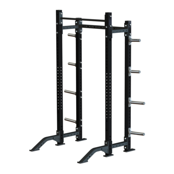
3. Product Information Squat Stand (HDW-SQST) Product Specs Size (L x W x H*): in = 53 x 48 x 91 cm =135 x 122 x 231 Live Area (L x W): in = 84 x 120 cm = 213 x 305... -
Page 50: Half Rack (Hdw-Hr)
Half Rack (HDW-HR) Product Specs *Size (L x W x H): in = 50 x 48 x 91 cm =127 x 122 x 231 Live Area (L x W): in = 84 x 120 cm = 213 x 305 Rack Weight: 211 lbs 96 kg Max User Weight:... -
Page 51: Power Rack (Hdw-Pr)
Power Rack (HDW-PR) Product Specs *Size (L x W x H): in = 44 x 48 x 91 cm =112 x 122 x 231 Live Area (L x W): in = 120 x 120 cm = 305 x 305 Rack Weight: 224 lbs 102 kg Max User Weight:... -
Page 52: Combo Rack (Hdw-Hhcr, Hdw-Phcr, Hdw-Ppcr)
Combo Rack (HDW-HHCR, HDW-PHCR, HDW-PPCR) Half / Half Combo Rack (HDW-HHCR) Short Single Storage Long Single Storage Short Double Storage Long Double Storage 15" Depths + 1 21" Depths + 1 15" Depths + 2 21" Depths + 2 Upright Upright Uprights Uprights... - Page 53 General Product Specs Max User Weight: 350 lbs 159 kg *Max Training Weight: 675 lbs 306 kg Training Upright Heights: in = 86 or 91 cm = 218 or 231 Storage Upright Height: in = 86 cm = 218 NOTE: •...
- Page 54 Half / Half Combo Rack (HDW-HHCR) with Long Double Storage Page 52 of 69...
- Page 55 Power / Half Combo Rack (HDW-PHCR) with Long Double Storage Page 53 of 69...
- Page 56 Power / Power Combo Rack (HDW-PPCR) with Long Double Storage Page 54 of 69...
-
Page 57: Exercise
4. Exercise General Exercise Information Intended Use The intended commercial use of this machine is to aid exercise and improve general physical fitness. Multiple exercises can be performed using this product. It is the responsibility of the owner to ensure exercisers understand general use and only perform recommended exercises that do not compromise the stability of the product or put the user as risk. -
Page 58: Maintenance Procedures
5. Maintenance Procedures Maintenance Schedule ACTION DAILY WEEKLY MONTHLY AS NEEDED CLEAN Guide Rods Shrouds Hand Grips Frames INSPECT Accessories Paint Cable Hardware Frame Shrouds LUBRICATE Guide Rods Clean • Guide rods with a cotton cloth. • Frames with a standard, non-abrasive, wax finish. Inspect •... - Page 59 • Check cables for stretch and adjust as necessary by loosening the large Jam Nut on top of the weight stack and by screwing in the Threaded Plug until cable is tight and the weight stack pin goes in all holes easily. Securely tighten the large Jam Nut when finished.
-
Page 60: Warranty
6. Warranty What is Covered This Life Fitness Family of Brands commercial exercise equipment product is warranted to be free of all defects in material and workmanship. Who is Covered The original purchaser or any person receiving the product as a gift from the original purchaser. Who Pays Transportation and Insurance For Service If the Product or any covered part must be returned to a service facility for repairs, We, Life Fitness Family of Brands, will pay all transportation and insurance charges for the first year. -
Page 61: How To Obtain Product Service
Item 5 Years 3 Years 1 Year 90 Days Frame Hardware / Mechanical Items Not Specified How to Obtain Product Service For CUSTOMER Service within the United States and Canada: 1-800-351-3737 or customersupport@lifefitness.com Please call Monday through Friday from 7:00 a.m. to 6:00 p.m. Central Standard Time, and tell them your name, address, and serial number of your Product. -
Page 62: Cable Handling Guide
7. Cable Handling Guide Cable Connections, Seating, and Installation Cable Connections with threaded cable ends are required to be installed and maintained following the specifications identified below. Failure to follow these specifications can lead to the dislocation of the threaded cable during use and can cause serious injury. -
Page 63: Cabling Procedure
Cabling Procedure Direct Link 1. Thread the cable into the head plate assembly at least to the jam nut. 2. Cycle the machine to ensure that it is in proper working order. 3. Check the cable to ensure there is proper tension. 4. -
Page 64: Tensioning Cable
8. Tighten the jam nut toward the head plate assembly and frame anchor. 9. Torque the jam nuts to 20-25 FT-LBS. (27.2 - 34.0 Nm). Tensioning Cable Cable should have enough tension so it stays seated into the pulley but not so tight that it pulls the head plate off the weight plate below it. - Page 65 BULGING: Internal wire rope strands can break within and coil causing a bulge to appear. Cable should retain same outside diameter throughout. FRAYED/EXPOSED WIRE ROPE: Any exposed wire rope protruding through the casing or at either end. FLATTENED: Section of cable is compressed and will not retain its shape (outside diameter).
-
Page 66: Bolt To Floor Guide Introduction
Bolt to Floor Qualifications Unit Recommended Bolt to Required Bolt to Floor Floor HDW-SQST Squat Stand HDW-HR Half Rack HDW-PR Power Rack HDW-PR Power Rack (with weight plate storage uprights) HDW-HHCR Half/Half Combo Rack HDW-HHCR Half/Half Combo Rack (with stability feet) -
Page 67: Anchor Types
Carpeting If bolted down to carpet flooring, be sure to use a box cutter knife to cut the carpet threads around each foot. This will help avoid the carpet threads from being wrapped around and pulled by the drill bit. Competitor Product The bolt down guidelines and procedures for Life Fitness products were determined by the company’s Engineering and Installation Development groups. -
Page 68: Pullout Force
Item Description Anchor Concrete Thickness Anchor Embedment into Concrete Thickness Drill Depth Beyond Anchor Thickness Distance of Anchor to Concrete Edge Flooring (wood/tile/rubber/screed) Thickness Base Plate Thickness (See Foot Dimensions) Pullout Force Life Fitness specifies Hilti ™ static and dynamic anchors. According to the anchor manufacturer, the recommended design pullout force (in tension) for the specified anchors, when properly installed in cracked concrete, is provided in the side table. -
Page 69: Anchor Procedure
Anchor Procedure 1. Place unit into position to be mounted and cycle unit to set its stance. 2. Wearing protective glasses, drill down into flooring perpendicularly to the required depth, ensuring that the foot thickness of the unit is being accounted for; refer to Anchor Specifications and Foot Dimensions. NOTE: Use 3/8"... - Page 70 5. Tighten to 30 foot-pounds for Imperial (45Nm for Metric), assuring there are at least 3 threads left exposed. Item Description Qty. Torque Wrench Anchor Assembly 6. If necessary, cut extra length from top of anchor with a rotary tool leaving proper concrete engagement, torque requirements and at least 3 exposed threads.
-
Page 71: Foot Dimensions
Foot Dimensions Use below image to determine foot height thickness. Page 69 of 69...
Need help?
Do you have a question about the HDW-SQST and is the answer not in the manual?
Questions and answers