
Related Manuals for Hammer Strength HDU-ADAT


Summary of Contents for Hammer Strength HDU-ADAT
- Page 1 Heavy Duty Cable Systems Owner's Manual/Assembly Instructions HDU‑ADAT, HDU‑ADCC, HDU‑ADDPR, HDU‑ADPSF, HDU‑ATWR, HDU‑CCM, HDU‑CCOR, HDU‑DPR, HDU‑PCOR, HDU‑PSF 1025722-0001 REV AA...
- Page 3 Corporate Headquarters Columbia Centre III, 9525 Bryn Mawr Avenue, Rosemont, IL 60018 • U.S.A. 847.288.3300 • FAX: 847.288.3703 Service phone number: 800.351.3737 (toll-free within U.S.A., Canada) Global Website: www.lifefitness.com International Offices AMERICAS EUROPE, MIDDLE EAST, and AFRICA (EMEA) All Other EMEA Countries and Distributor Business EMEA* North America Belgium, Netherlands, and Luxemburg...
- Page 4 User and Service Documents Link https://lfn.fit/KnowledgeBase https://lfn.fit/SupportDocuments Additional information is available online using the links above. أ علاه إل ر إبط باستخدإم إ لإ ن تر نت على إضافية معلومات تتوفر 点击上面的链接可在线获取更多信息。 Flere oplysninger er tilgængelige online gennem linket ovenfor. Bijkomende informatie is online beschikbaar via bovenstaande link.
-
Page 5: Table Of Contents
© Copyright 2024, Life Fitness, LLC. All Rights Reserved. Life Fitness, Hammer Strength, Cybex, ICG and SCIFIT are registered trademarks of Life Fitness, LLC and its affiliated companies and subsidiaries. Disclaimer: Images and specifications are current as of the date of publication and are subject to change. - Page 6 © Copyright 2024, Life Fitness, LLC. All Rights Reserved. Life Fitness, Hammer Strength, Cybex, ICG and SCIFIT are registered trademarks of Life Fitness, LLC and its affiliated companies and subsidiaries. Disclaimer: Images and specifications are current as of the date of publication and are subject to change.
-
Page 7: Safety Information
1. Safety Safety Information It is the sole responsibility of the purchaser of Life Fitness products to read the owner’s manual and warning labels and instruct all individuals, whether they are the end user or supervising personnel, on proper usage of the equipment. UNDERSTANDING EACH AND EVERY WARNING TO THE FULLEST IS IMPORTANT. - Page 8 • Equipment Maintenance - Preventative maintenance is the key to smooth operating equipment as well as to keep your liability to a minimum. Equipment needs to be inspected at regular intervals. • Ensure that any person(s) making adjustments or performing maintenance or repair of any kind is qualified to do so.
-
Page 9: Product Labels
Product Labels General Warning Carriage Adjust Pull Pin Engagement Bar Catch Warning Maximum Capacity 680 lbs Serial Number Maximum Capacity 1485 lbs Bar Catch Height FCC Compliant Page 7 of 55... -
Page 10: Label Locations
Label Locations Accessory Tower (HDU-ADAT, HDU-ATWR) Item Description Qty. Maximum Capacity 680 lbs Maximum Capacity 1485 lbs FCC Compliant Serial Number Page 8 of 55... - Page 11 ADD (HDU-ADAT, HDU-ADCC (shown), HDU-ADDPR, HDU-ADPSF) Item Description Qty. Maximum Capacity 680 lbs Serial Number FCC Compliant Carriage Adjust Pull Pin Engagement General Warning Page 9 of 55...
- Page 12 Cable Column (HDU-ADCC, HDU-CCM (shown), HDU-CCOR) Item Description Qty. Carriage Adjust General Warning Pull Pin Engagement FCC Compliant Serial Number Page 10 of 55...
- Page 13 CORE (HDU-CCOR (shown), HDU-PCOR) Item Description Qty. Maximum Capacity 680 lbs Maximum Capacity 1485 lbs Serial Number FCC Compliant Pull Pin Engagement Carriage Adjust General Warning Page 11 of 55...
- Page 14 Dual Pulldown-Row (HDU-ADDPR, HDU-DPR) Item Description Qty. General Warning FCC Compliant Serial Number Page 12 of 55...
- Page 15 Perimeter Side Frame (HDU-PCOR, HDU-PSF) Item Description Qty. Bar Catch Warning Bar Catch Height General Warning Serial Number Page 13 of 55...
-
Page 16: Assembly
2. Assembly Component and Hardware List HDU-ATWR Components Item Description Qty. Upright Assembly (8 ft) Crossmember (42 in) Foot Slipper Hardware Kit - HDU 1 Optional Dumbbell Storage (42 in) Optional Dual Rail Storage (42 in) Optional Accessory Storage (42 in) Optional 2-Pipe Storage (42 in) NOTE: Uprights also available in 9 foot heights HDU-ATWR Hardware List... - Page 17 HDU-CCM Components Item Description Qty. Tower Assembly (8 ft) 15lb (6.8kg) Weight Plate Foot Slipper Hardware Kit Weight Stack Label (lb or kg) Short Handle Assembly Long Handle Assembly NOTE: Tower assembly also available in 9 foot heights HDU-CCM Hardware List Item Description Qty.
- Page 18 HDU-DPR Components Item Description Qty. Tower Assembly (8 ft) Bench Assembly Bench Slipper 15lb (6.8kg) Weight Plate Lat Bar Assembly Hardware Kit Foot Slipper Weight Stack Label (lb or kg) Row Handle NOTE: Tower assembly also available in 9 foot heights HDU-DPR Hardware List Item Description...
- Page 19 ADD Components (HDU-ADAT, HDU-ADCC (shown), HDU-ADDPR) Item Description Qty. Tower Assembly (Accessory/Cable Column (shown)/Pulldown Row) Upright Assembly Corner Brace Weldment Cross Member (42 in) Optional Super Duty Cross Member (42 in) Optional Hammer Strength Cross Member (42) 6 Inch Cross Member Weldment 15lb (6.8kg) Weight Plate...
- Page 20 Upright Assembly Optional Pullup Weldment Optional Pullup/Cross Member (42 in) Optional Super Duty Cross Member (42 in) Optional Hammer Strength Cross Member (42) 6 Inch Cross Member Weldment Optional Dual Rail Storage (42 in) Optional Accessory Storage (42 in) Page 18 of 55...
-
Page 21: Tools Required
Item Description Qty. Optional Dumbbell Storage (42 in) Optional 2-Pipe Storage (42 in) Foot Slipper 15lb (6.8kg) Weight Plate Weight Stack Label (lb or kg) Long Handle Assembly Short Handle Assembly Hardware Kit • Storage and cross members also available in 72 and 84 inch lengths. CORE Hardware List (HDU-ADCC shown) Item Description... -
Page 22: Assembly Procedure
Assembly Procedure HDU-ATWR Assembly 1. Move unit into position and attach foot slipper to each upright. Item Description Qty. Upright Assembly Foot Slipper 2. With the rectangle tubing nuts in the upright assemblies, attach crossmember and trays to the upright assemblies and hand tighten. - Page 23 HDU-DPR Assembly 1. With the unit in place, attach the foot slippers to the bench and tower assemblies. Item Description Qty. Bench Assembly Bench Slipper Tower Assembly Foot Slipper 2. With the rectangle tubing nuts in the tower assembly, attach bench assembly to the tower assembly and tighten to 45-50 ft-lbs (61.0-67.8 nm).
- Page 24 5. Open the snap link and slide attachment into place. Item Description Qty. Attachment (Row Handle) Snap Link NOTE: Repeat for lat bar assembly. Page 22 of 55...
- Page 25 Weight Stack Assembly 1. If equipped with shrouds, carefully remove the rear shroud from the front shroud's channels. Item Description Qty. Front Shroud Rear Shroud Weight Stack Cushion NOTE: Make sure weight stack cushions are in place. 2. Pull guide rod retainers/springs down and away from tower to release the guide rods. Item Description Qty.
- Page 26 4. Carefully tilt weight plates around the front shrouds and onto the guide rods. Item Description Qty. Weight Plate see below Front Shroud Guide Rod NOTE: If needed, tighten the two 1/2-13 X 1.25 screws at the base of the front shrouds before too many weight plates are added.
- Page 27 Item Description Qty. Weight Stack Weight Stack Label (lb or kg) ADD Assembly (HDU-ADAT, HDU-ADDPR, HDU-ADCC) 1. Connect the upper tower/upright assembly and upright/cross member assemblies with the 6 inch connecting weldment and hand tighten hardware. Item Description Qty.
- Page 28 2. Connect the upper tower/upright assembly and upright/cross member assemblies with the corner brace weldment and hand tighten hardware. Item Description Qty. Tower/Upright Assembly Screw, 1/2-13 X 4.5 Backing Washer Cross Member Assembly Washer, Step, 1/2 in, 0.57 in 1/2 in Lock Nut Corner Brace Weldment 1/2 in Star Washer 3.
- Page 29 CORE Assembly (HDU-CCOR, HDU-PCOR) 1. Connect the upper tower/upright assembly and upright/cross member assemblies with the 6 inch connecting weldment and hand tighten hardware. Item Description Qty. Rectangle Tubing Nut, 11GA, 3" Tower/Upright Assembly 6 Inch Cross Member Weldment Screw, 1/2-13 X 1.25 1/2 in Star Washer Upright/Cross Member Assemblies 2.
- Page 30 4. Add optional trays to uprights and hand tighten hardware. Item Description Qty. Screw, 1/2-13 X 4.5 Backing Washer Tower Assembly Washer, Step, 1/2 in, 0.57 in 1/2 in Lock Nut Optional Tray Assembly 5. Tighten hardware with backing washers to 20-25 ft-lb (27.1-33.9 nm) Tighten all other hardware to 45-50 ft-lb (61-67.8 nm).
- Page 31 Mount Types Cable towers have various mounting applications: Item Description Application Mullet iD Mullet Installation and ADDs for iD Racks Mullet NX Mullet Installation for NX Racks Sandwich Rack Connectors Square Face T Connection Stand Alone HDU-DPR only Mullet iD Assembly 1.
- Page 32 2. Connect the corner brace weldment to the tower and iD assemblies. Hand tighten hardware. Item Description Qty. Tower Assembly Screw, 1/2-13 X 4.5 Backing Washer iD Assembly Washer, Step, 1/2 in, 0.57 in 1/2 in Lock Nut Corner Brace Weldment 1/2 in Star Washer 3.
- Page 33 2. Connect the lower tower assembly and storage assembly with connecting weldment and hand tighten hardware. Item Description Qty. Tower Assembly Rectangle Tubing Nut, 11GA, 3" 1/2 in Star Washer Screw, 1/2-13 X 1.25 Lock Nut, 1/2" NX Storage Assembly Backing Washer Screw, 1/2-13 X 4.5 6 Inch Cross Member Weldment...
- Page 34 Square Face Assembly 1. Connect the tower assembly to a cross member with corner brace weldments and hand tighten hardware. Item Description Qty. Tower Assembly Crossover Weldment 1/2 in Lock Nut 1/2 in Star Washer Backing Washer Corner Brace Weldment Washer, Step, 1/2 in, 0.57 in Screw, 1/2-13 X 4.5 2.
-
Page 35: Product Information
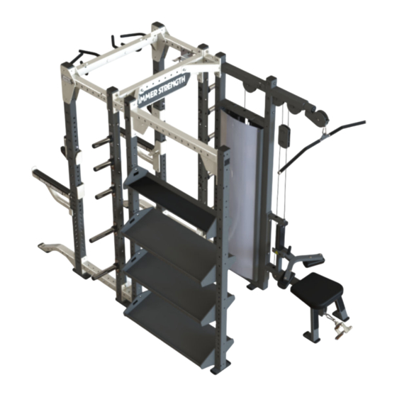
3. Product Information Accessory Tower: HDU-ADAT, HDU-ATWR (shown) Product Specs *Size (L x W): in = 49 x 17 cm =125 x 44 Live Area (L x W): in = 42 x 24 cm = 107 x 61 Upright Heights:... -
Page 36: Add: Hdu-Adat, Hdu-Adcc (Shown), Hdu-Addpr, Hdu-Adpsf
ADD: HDU-ADAT, HDU-ADCC (shown), HDU-ADDPR, HDU-ADPSF Product Specs *Tray Size (L x W): in = 49 x 17 cm =125 x 44 *Cable Column Size (L x W): in = 46 x 9 cm =117 x 23 Tray Live Area (L x W):... - Page 37 Page 35 of 55...
-
Page 38: Cable Column: Hdu-Ccm (Shown), Hdu-Ccor
Cable Column: HDU-CCM (shown), HDU-CCOR Product Specs *Size (L x W): in = 46 x 9 cm =117 x 23 Live Area (L x W): in = 102 x 69 cm = 259 x 175 Upright Heights: in = 96 or 108 cm = 244 or 274 8 Foot Height Weight: 648 lbs... -
Page 39: Core: Hdu-Ccor (Shown), Hdu-Pcor
CORE: HDU-CCOR (shown), HDU-PCOR Product Specs *Tray Size (L x W): in = 72 x 17 cm =183 x 43 *Cable Column Size (L x W): in = 46 x 9 cm =117 x 23 Tray Live Area (L x W): in = 72 x 36 cm = 183 x 92 Cable Column Live Area (L x W):... - Page 40 Page 38 of 55...
-
Page 41: Dual Pulldown Row: Hdu-Addpr, Hdu-Dpr (Shown)
Dual Pulldown Row: HDU-ADDPR, HDU-DPR (shown) Product Specs *Size (L x W): in = 64 x 48 cm =163 x 122 Live Area (L x W): in = 84 x 84 cm = 214 x 214 Upright Heights: in = 96 or 108 cm = 244 or 274 8 Foot Height Weight: 679 lbs... -
Page 42: Perimeter Side Frame: Hdu-Pcor, Hdu-Psf (Shown)
Perimeter Side Frame: HDU-PCOR, HDU-PSF (shown) Product Specs *Size (L x W): in = 52 x 40 cm =132 x 102 Live Area (L x W): in = 42 x 24 cm = 107 x 61 Upright Heights: in = 96 cm = 244 Upright Weight (each): 109 lbs... -
Page 43: Exercise
4. Exercise General Exercise Information Intended Use The intended commercial use of this machine is to aid exercise and improve general physical fitness. Multiple exercises can be performed using this product. It is the responsibility of the owner to ensure exercisers understand general use and only perform recommended exercises that do not compromise the stability of the product or put the user as risk. -
Page 44: Maintenance Procedures
5. Maintenance Procedures Maintenance Schedule ACTION DAILY WEEKLY MONTHLY AS NEEDED Frames INSPECT Accessories Paint Hardware Frame Clean • Frame with a mild soap and water. • Frames with a standard, non-abrasive, wax finish. Inspect • Hardware. Check for loosening. Tighten as required. •... - Page 45 Removal of Paint, Marking Pens, or Labels • Butyl cellosolve works well for removal of paints, marking pen inks, lipstick, etc. • Labels, stickers, etc. may be removed using kerosene. When the solvent will not penetrate sticker material, apply heat (hair dryer) to soften the adhesive and promote removal. GASOLINE SHOULD NOT BE USED. Page 43 of 55...
-
Page 46: Warranty
6. Warranty What is Covered This Life Fitness commercial exercise equipment product is warranted to be free of all defects in material and workmanship. Who is Covered The original purchaser or any person receiving the product as a gift from the original purchaser. Who Pays Transportation and Insurance For Service If the Product or any covered part must be returned to a service facility for repairs, We, Life Fitness, will pay all transportation and insurance charges for the first year. - Page 47 http://lifefitness.com/warranties Page 45 of 55...
-
Page 48: Cable Handling Guide
7. Cable Handling Guide Cable Terminations, Tensioning and Wear Guide Cable Connections with threaded cable ends are required to be installed and maintained following the specifications identified below. Failure to follow these specifications can lead to the dislocation of the threaded cable during use and can cause serious injury. -
Page 49: Tensioning Cable
3. When proper thread engagement is reached, tighten jam nut to 20-25 FT-LBS (27.2 - 34.0 Nm) using a 24mm wrench. Tensioning Cable Cable should have enough tension so it stays seated into the pulley but not so tight that it pulls the head plate off the weight plate below it. -
Page 50: Strength Cable Wear Guide
3. When proper thread engagement is reached, tighten jam nut to 20-25 FT-LBS (27.2 - 34.0 Nm) using a 24mm wrench. Strength Cable Wear Guide Replace cable at first sign of any of the following: FRACTURES: Casing can crack or fracture under strains during use. Any crack in the casing merits cable replacement even if no wire rope is exposed. -
Page 51: Insert Inspection
Insert Inspection Inspect insert within the strain-relief cable end assembly and replace if any sign of damage. 1. Check around plastic insert and the plastic housing for any excessive wear or damage. Item Description Qty. Plastic Insert Plastic Housing 2. Replace plastic insert if cracked, torn, separated, overly worn or damaged in any way. Item Description Status... -
Page 52: Bolt To Floor Guide Introduction
8. Bolt to Floor Guide Introduction Life Fitness designs its products to be stable when used as designed. Because strength training is dynamic, we cannot predict how users will ultimately use the products in all circumstances. Therefore, Life Fitness requires that strength training equipment be secured to a solid, level surface to stabilize and eliminate rocking or tipping over. -
Page 53: Anchor Type - Static
• Life Fitness installation teams are not permitted to anchor competitor equipment. Drilling It is also recommended to drill an additional 1/2” (12.7 mm) of depth beyond the length of the fastener being used to ensure that debris does not block the entry of the anchor. •... -
Page 54: Pullout Force
Item Description Anchor Concrete Thickness Anchor Embedment into Concrete Thickness Drill Depth Beyond Anchor Thickness Distance of Anchor to Concrete Edge Flooring (wood/tile/rubber/screed) Thickness Base Plate Thickness (See Foot Dimensions) Pullout Force Life Fitness specifies Hilti ™ static and dynamic anchors. According to the anchor manufacturer, the recommended design pullout force (in tension) for the specified anchors, when properly installed in cracked concrete, is provided in the side table. - Page 55 Anchor Procedure 1. Place unit into position to be mounted and cycle unit to set its stance. 2. Wearing protective glasses, drill down into flooring perpendicularly to the required depth, ensuring that the foot thickness of the unit is being accounted for; refer to Anchor Specifications and Foot Dimensions. NOTE: Use 3/8"...
- Page 56 5. Tighten to 30 foot-pounds for Imperial (45Nm for Metric), assuring there are at least 3 threads left exposed. Item Description Qty. Torque Wrench Anchor Assembly 6. If necessary, cut extra length from top of anchor with a rotary tool leaving proper concrete engagement, torque requirements and at least 3 exposed threads.
- Page 57 Foot Dimensions Use below image to determine foot height thickness. Page 55 of 55...
Need help?
Do you have a question about the HDU-ADAT and is the answer not in the manual?
Questions and answers