Table of Contents
Advertisement
Quick Links
Advertisement
Table of Contents

Related Manuals for Hammer Strength HD SPARC


Summary of Contents for Hammer Strength HD SPARC
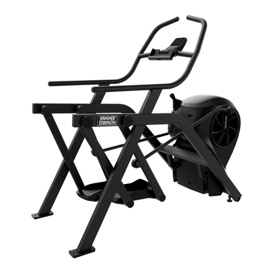
- Page 1 HD SPARC Owner's Manual PT‑SC 1018738-0001 REV AC...
- Page 3 Corporate Headquarters 10601 W Belmont Ave, Franklin Park, IL 60131 • U.S.A. 847.288.3300 • FAX: 847.288.3703 Service phone number: 800.351.3737 (toll-free within U.S.A., Canada) Global Website: www.lifefitness.com International Offices AMERICAS United Kingdom All Other EMEA Countries and Distributor Business EMEA* North America Life Fitness UK LTD Bijdorpplein 25-31...
- Page 4 User and Service Documents Link https://lifefitness9512.zendesk.com/hc/en-us https://www.lftechsupport.com/web/document-library/documents Additional information is available online using the links above. أ علاه إل ر إبط باستخدإم إ لإ ن تر نت على إضافية معلومات تتوفر 点击上面的链接可在线获取更多信息。 Flere oplysninger er tilgængelige online gennem linket ovenfor. Bijkomende informatie is online beschikbaar via bovenstaande link.
-
Page 5: Table Of Contents
2XL Corporation. PureGreen 24 is a trademark of Pure Green. © Copyright 2021, Life Fitness, LLC. All Rights Reserved. Life Fitness, Hammer Strength, Cybex, ICG and SCIFIT are registered trademarks of Life Fitness, LLC and its affiliated companies and subsidiaries. Brunswick and related trademarks used under license from Brunswick Corporation. - Page 6 FCC Compliance Information Changes or modifications to this unit not expressly approved by the party responsible for compliance could void the user’s authority to operate the equipment. This equipment has been tested and found to comply with the limits for a Class B digital device, pursuant to part 15 of the FCC Rules.
-
Page 7: Safety Instructions
1. Safety Safety Instructions Read all instructions before use. Please take special note of the following safety instructions and important points prior to choosing a location and beginning assembly of the product. Operating Warnings WARNING: This product can expose you to chemicals including Di-2-ethylhexyl-phthalate, which is known to the State of California to cause cancer and birth defects or other reproductive harm. - Page 8 • This appliance is not intended for use by persons (including children) with reduced physical, sensory, or mental capabilities, or lack of experience or knowledge unless they have supervision or been given instruction concerning the use of the appliance by a person responsible for their safety. •...
-
Page 9: Consignes De Sécurité
Consignes de sécurité Veuillez lire toutes les instructions avant usage. Prêtez une attention toute particulière aux instructions de sécurité ci-dessous avant de choisir un emplacement et de commencer à assembler votre produit. Avertissements relatifs au fonctionnement AVERTISSEMENT : This product can expose you to chemicals including Di-2-ethylhexyl-phthalate, which is known to the State of California to cause cancer and birth defects or other reproductive harm. - Page 10 • Cet appareil n’est pas destiné à être utilisé par des personnes ou des enfants présentant des capacités physiques, sensorielles ou mentales réduites, ou un manque d’expérience et de connaissances, sauf en cas de supervision ou d’instructions relatives à son utilisation par une personne responsable de leur sécurité. •...
-
Page 11: Assembly
2. Assembly Choosing and Preparing Site Product Dimensions Size (L x W x H) in. = 71 x 34.7 x 60.6 cm = 180 x 88 x 154 Free Area (L x W x H) in. = 106.6 x 58.7 x 60.6 cm = 270.5 x 149 x 154 Free Area Before assembling the unit, verify the chosen site meets the following criteria:... -
Page 12: Assembly Procedure
Handrail Assembly Foot Pad Owner’s Manual Hardware Item Description Qty. Hardware Kit, HD SPARC Bolt, .312-18 x .5, HXS Battery, D Cell 1.5V Alkaline Tools Required • Flat head screwdriver • 1/2” Socket with Torque wrench • 1/2” Open end wrench •... - Page 13 Install Handrail Assembly 1. Place the handrail assembly into position on the base assembly. 2. Install the bolts securing the handrail assembly to the base assembly using a 1/2" socket with torque wrench. Item Description Qty. Base Assembly Handrail Assembly Bolt, .312-18 x .5, HXS Plastic Sheet Tighten hardware to 13 ft-lb (17.6 Nm).
- Page 14 2. Install the two batteries as shown. NOTE: The batteries must be installed in the proper direction. Item Description Qty. Console Battery, D Cell 1.5V Alkaline 3. Insert the two battery access cover tabs into console. Item Description Qty. Console Battery Access Cover 4.
- Page 15 Install Foot Pads Have one person lift the unit while a second person places a foot pad under each of the two back feet. Item Description Qty. Foot Pad Level Unit This procedure will level the unit by evenly adjusting the weight on the rear feet. Leveling the unit will eliminate rocking during use.
- Page 16 3. Grasp the other side of the frame and slowly lift the rear foot off the floor. Lower rear foot to the floor. Make note of either rear foot lifting off the floor easier than the other. If both rear feet lift off the floor evenly, secure both leveling foot jam nuts against the frame post using a 9/16” open-end wrench.
-
Page 17: Setup
Install Water Bottle Holder Standard bicycle water bottle holders can be mounted to the frame. Water bottle holders are not supplied by Hammer Strength. 1. Remove screws on the side of the handrail assembly using a 4mm Allen wrench. Save screws. Item Description Qty. -
Page 18: Calibrate Resistance Level
Setup Complete Calibrate Resistance Level Perform this calibration procedure to display the correct resistance levels throughout the full range of the resistance lever. This is required when installing the unit, replacing the console or sensor board, or if the unit has been disassembled. - Page 19 6. Press the GO/Enter key. 7. Verify level meter is at LEVEL 1 and resistance is low. 8. Verify WATTS are displayed on display screen. 9. Move the resistance lever up to LEVEL 5. Verify resistance is higher than LEVEL 1. 10.
-
Page 20: Operation
3. Operation Individual Human Power Versus Mechanical Power WARNING: Power difference. The individual human power which is required to carry out an exercise can be different than the mechanical power displayed. Intended Use The intended commercial use of this machine is to aid exercise and improve general physical fitness. Terms Used This section lists some of the common terms and symbols used in this chapter. -
Page 21: Resistance Lever
Item Control Name Description GO/ENTER KEY Start Circuit workout. Enter settings during Interval workout setup. Select settings in Toolbox screen, moves forward in menu. STOP/REVIEW KEY Ends a workout. Resets console. Navigates back in Setup menu. ARROW DOWN Adjust values down. Navigate down in menus, languages, defaults, and other settings. -
Page 22: Quick Operation Guide
2. Stop striding. 3. Wait until foot plates come to a complete stop. 4. Continue to hold handrails while carefully stepping off unit. Quick Operation Guide Maximum user weight is 350 lbs. (158 kg). The following is a quick overview of the operation of the unit. 1. - Page 23 Interval Workout Overview Interval Mode allows the user to predefine the duration work and rest intervals as well as the total number of sets to be performed. Display Description WORK Exercise during this interval REST Rest during this interval SETS Remaing number of sets in workout LEVEL Displays current resistance level...
-
Page 24: Results
Results As the user exercises, the unit keeps track of and displays the following data: PEAK WATTS Highest workload energy exertion. AVG WATTS Average workload energy exertion. AVG SPM (Strides per The average number of strides per minute. Minute) TIME The total time you've been working out. -
Page 25: Maintenance
4. Maintenance All preventive maintenance activities must be performed on a regular basis. Performing routine preventive maintenance actions can aid in providing safe, trouble-free operation of all Life Fitness equipment. Life Fitness is not responsible for performing regular inspection and maintenance actions for your machines. Instruct all personnel in equipment inspection and maintenance actions and also in accident reporting and recording. - Page 26 Replace the batteries if LOW BATTERY appears at start up, Storage or long non-use periods When not using product for more than six months, the batteries should be removed to prevent leakage. Check Battery Level The battery level can be checked through the console. 1.
- Page 27 Replace with two, D cell, alkaline batteries only. Always use two new equal batteries, of the same current rating and manufacturer. 1. Remove the battery access cover by loosening the screw using a flat head screwdriver. The screw will remain in the battery access cover.
-
Page 28: Service Schedule
4. Insert the two battery access cover tabs into console. Item Description Qty. Console Battery Access Cover 5. Tighten the battery access cover screw using a flat head screwdriver. NOTE: Dispose of batteries safely after replacement or before unit disposal. Service Schedule All maintenance activities shall be performed by qualified personnel. - Page 29 Contact qualified service technician to perform the following procedures. 1. Inspect incline assembly. 2. Replace any worn parts. 3. Lubricate incline bushings. Page 27 of 30...
-
Page 30: Product Specifications
5. Product Specifications Classification EN ISO 20957 Class S (Studio) Accuracy Assembled Length 71" (180 cm) Assembled Width 34.7" (88 cm) Assembled Height 60.6" (154 cm) Weight of Product 265 lbs. (120 kg) Shipping Weight 330 lbs. (150 kg) Resistance Levels 1-10 levels of brake resistance Resistance Range Fan 0-1000 watts, Resistance Lever (ECB) adds additional 0-400 watts... -
Page 31: Warranty
6. Warranty What is Covered This Life Fitness Family of Brands commercial exercise equipment product is warranted to be free of all defects in material and workmanship. Who is Covered The original purchaser or any person receiving the product as a gift from the original purchaser. Warranty will be voided on subsequent transfers. -
Page 32: Changes In Warranty Not Authorized
This warranty gives you specific legal rights, and you may have other rights which vary from state to state and country by country. Warranty Information Base 3 years 2 years 1 Year HD SPARC Parts and Frame Electrical Labor Warranties outside the U.S. may vary. Page 30 of 30...
Need help?
Do you have a question about the HD SPARC and is the answer not in the manual?
Questions and answers