Table of Contents
Advertisement
Quick Links
INSTRUCTIONS - PARTS LIST
This manual contains important
warnings and information.
READ AND RETAIN FOR REFERENCE
INSTRUCTIONS
PRECISION MIX™
Proportioning Controller
For Proportional Mixing Of Plural Component Coatings
+ 5 Volts, 1.4 Amps; + 12 Volts, 0.7 Amps; -12 Volts, 0.002 Amps
Model: 949-999
For use only in non-hazardous locations. Maximum
applied relay voltage shall not exceed +24 volts. Do
not operate in hazardous locations, as defined in
article 500 of the National Electrical Code (USA).
PATENT PENDING
Part No. 112-434 Black Pendant
Part No. 112-435 Red Pendant
The red pendant is the same as the black pendant
except the setup options are not accessible.
GRACO INC. - EAS
P.O. Box 1441
©
COPYRIGHT 1997, GRACO INC.
684-015
MINNEAPOLIS, MN 55440-1441
Advertisement
Table of Contents

Subscribe to Our Youtube Channel
Related Manuals for Graco PRECISION MIX 949-999


Summary of Contents for Graco PRECISION MIX 949-999
- Page 1 Part No. 112-434 Black Pendant Part No. 112-435 Red Pendant The red pendant is the same as the black pendant except the setup options are not accessible. GRACO INC. - EAS P.O. Box 1441 MINNEAPOLIS, MN 55440-1441 © COPYRIGHT 1997, GRACO INC.
-
Page 2: Warnings
WARNINGS Serious injury, explosion, fire or electrostatic shock can occur if the precautions below are not followed. Read and understand all instruction manuals, tags, and warning labels before operating equipment. Electrical equipment shall only be installed, operated, and serviced by trained, qualified personnel who shall be fully conversant with the requirements stated within this instruction manual. -
Page 3: Table Of Contents
Be sure that all fluids and solvents used are chemically compatible with the wetted parts of each of your Only use genuine Graco replacement parts when system’s components. Always read the manufacturer’s servicing the Precision Mix™. -
Page 4: How The Precision Mix™ Works
How the Precision Mix™ Works The standard Graco Precision Mix™ can blend most The following is a typical ratio cycle: two-component epoxy or polyurethane paints. • First, the component A (resin) dispense valve Precision Mix™ is not for use with “quick-setting” paints opens, and the fluid begins to flow into the (those with a pot life of less than 15 minutes). - Page 5 FUNCTIONAL DIAGRAM - COMPONENT A (RESIN) DISPENSE A Component A (Resin) Supply Line B Fluid Filter, 100 mesh minimum C Check Valve D Flow Meter E Component A (Resin) Valve Air Purge Valve G Fluid Shut-off Valve H Ratio Check Valve Component B (Catalyst) Supply Line K Component B (Catalyst) Valve Solvent Purge Valve...
-
Page 6: Typical Installation
Typical Installation * IMPORTANT: Electrical connections must comply with all national, state, and local codes NON-HAZARDOUS HAZARDOUS HAZARDOUS AREA AREA AREA Air Hose AE Supply Tank, Component A Air Supply Line Main Power Switch (Resin) Fluid Filter (100 mesh 115V 60 Hz Electrical Supply AF Supply Tank, Component B minimum) and fluid... -
Page 7: Installation
Contact Graco for information on fluid the fluid inlets to the Precision Mix™, to reduce pressure regulators. pulsation and pressure. Contact Graco for information on fluid pressure regulators. For maintenance and safety, you must install a ball valve between each supply line and the Precision Mix™. - Page 8 +12 volt, 0.5 amp; -12 volt, 0.5 amp grounded electrical supply. Meter cables must be connected as shown in Fig 4. Follow the Installation Schematic provided by Graco. Failure to properly connect the grounded conductor and shield may cause incorrect signals.
- Page 9 Connect the pendant cable to the 9-pin controller Connect the 24 VDC meter cables to terminals connector marked PENDANT. inside the controller enclosure as shown on the prints provided by Graco. NOTE: The NEMA enclosure bulkhead has a 6-pin connect for the pendant.
-
Page 10: Operator Control And Indicators
There are no operator controls on the controller itself. SETUP is F2, BAT is F3, and GTOT is F4. Two remote devices provide operator interface; these are the Operator Switch and the Pendant. GRACO Operator Switch (See Fig 6) PRECISION MIX™ There are three operator input settings: REV. -
Page 11: Pendant Screens
Pendant Screens NOTE: The keys indicated after the screen will move you to the next screen that is shown, unless otherwise indicated Run Screens TARGET (left hand column) is the desired volumes of Target/Actual Display Component A and Component B that the controller will TARGET ACTUAL (cc) maintain. - Page 12 Pendant Screens Run Screens (continued) Tank Volume This screen can be used to display how much fluid is left in CAT TANK=0000.0 GAL the catalyst feed tank (CAT TANK) and the resin feed tank RES TANK=0000.0 GAL (RES TANK). By pressing the CAT or RES key you will see a screen that looks like the one of the two following screens.
- Page 13 Main Title Screen This screen can only be accessed by pressing the unmarked GRACO key in the F5 location on the black pendant. This screen PRECISION MIX™™ shows the Revision No. of the software. It will also show the REV.
- Page 14 Pendant Screens Setup Screens (continued) B Dispense Time The B Dispense Time screen functions the same way as the B DISPENSE TIME A Dispense Time screen, except it is measuring the amount LIMIT IS XXX SEC of time it takes to dispense Component B. NEW VALUE? XXX QUIT Press QUIT...
- Page 15 Pendant Screens Setup Screens (continued) Purge Component A The purge sequence consists of two purge valves, one for PURGE A Component A and one for Component B, alternating on and TIME IS XX.X SEC off. The value you enter for PURGE A determines how long NEW VALUE? XX.X the Component A purge valve is open for each dispense QUIT...
- Page 16 Pendant Screens Setup Screens (Continued) Number of Purge Cycles With this screen, you select how many times the purge PURGE SEQUENCE sequence shifts between Component A purge and EQUALS XX CYCLES Component B purge when the Operator Switch is set to NEW VALUE? XX PURGE.
- Page 17 Pendant Screens Setup Screens (Continued) Minimum Flow Rate Limit With this screen, you set the minimum allowable flow MINIMUM FLOW rate of the Precision Mix™. Minimum flow rate is LIMIT IS XXXX cc/M calculated by measuring the total time of a cycle. If the NEW VALUE? XXXX flow rate drops below the allowable setting, an alarm will QUIT...
- Page 18 Pendant Screens Setup Screens (Continued) Catalyst Tank Limit Display These two screens allow you to select whether the CAT LIMIT DISPLAYED Catalyst Tank Volume feature in the run screen (refer to page 12) is turned on or off. If it is turned off, the CHANGE? catalyst tank display will not appear in the run screens.
- Page 19 Pendant Screens Setup Screens (Continued) Change Installation Title Screen If you want to change the program in the installation CHANGE INSTALLATION? category, press the YES key. If you do not want to RECIPE 00 change the program in the installation category, press the NO key to return to the Setup Ratio Title screen (on QUIT page 13).
- Page 20 Pendant Screens Setup Screens (Continued) Component A Flow Meter Calibration Factor Since flow meters come in many different sizes and A FLOWMETER styles, it is necessary to tell the Precision Mix™ VALUE IS .XXX Control what size the flow meters are so it can NEW VALUE? >XXX properly read the electrical pulse the flow meter sends TEST...
- Page 21 Pendant Screens Setup Screens (Continued) Component B Flow Meter Calibration Factor The Component B Flow Meter Calibration Factor B FLOWMETER screens and the Solvent Flow Meter Calibration VALUE IS .XXX Factor screens function the same as the Component NEW VALUE? .XXX A Flow Meter Calibration Factor screen on page 20.
- Page 22 Precision Mix™ Alarm Descriptions If the machine stops from an alarm condition, the Overdose B associated alarm output will be active. The alarm When this alarm displays, the Precision Mix™ has outputs are described below. In addition, the alarm light continued dispensing fluid on the Component B side on the pendant blinks and a relevant message is after the valve has shifted to the Component A side.
-
Page 23: Software Screen Map With No Recipes
684-015... -
Page 24: Software Screen Map With Recipes
684-015... -
Page 25: Precision Mix™ Alarm Descriptions
Precision Mix™ Alarm Descriptions Tank Empty Alarm Output CAT TANK=0000.0 GAL RES TANK=0000.0 GAL Any of the following conditions will set this alarm: Cat Tank Empty When this alarm displays, the Precision Mix™ has dispensed the amount of Component B that was entered into the Catalyst Tank Volume screen. -
Page 26: Setting The Clock
Press the blank key in the upper right corner of the pendant once, to get to the Main Title screen. Enter a 2 digit value (date) and the pendant will automatically scroll to the next screen. GRACO YEAR=93 PRECISION MIX™ MONTH=08 REV. -
Page 27: New Precision Mix™ Software
New Precision Mix™ Software To remove the software chip without an extraction tool, WARNING carefully pry the chip out evenly on both sides. See fig To reduce the risk of electric shock, the power to the Precision Mix™ Controller must be off before you begin to change the software. -
Page 28: Operation
Operation The following instructions generally presume a Emergency Flush Procedure standard system using pressure supply tanks for the paint components and solvent, and air spray guns. If the electrical power is interrupted, the system can be Also see Optional System Arrangements on page 7 purged by using the following procedure: for possible variations and their effect on the instructions. - Page 29 Operation Remove any air from the fluid lines of the system: 13. Operation of the Precision Mix™ is controlled by the operation of the spray gun. When the gun is Shut off the air to the gun by closing the triggered, the dispense valves open and allow the air regulator on the Precision Mix™.
- Page 30 However, it is a good practice to check new values. with Graco periodically to see if hardware or software updates are available. Turn ON the main power switch and switch to MIX.
-
Page 31: Electrical Schematics
Precision Mix™ Controller Electrical Schematic 684-015... -
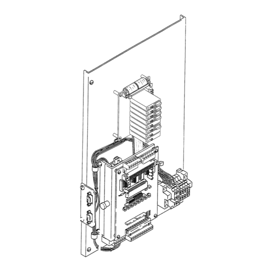
Page 32: Typical Controller Component Guide
Typical Controller Component Guide Typical Controller Typical I/O Board Terminal Strip Typical I/O Board Flow Meter Card Pendant Socket Flowmeter Socket 684-015... -
Page 33: 111-663 Computer Card
111-663 Computer Card Flow Meter Card Plug (Front View) Pendant Plug (Front View) Pendant Plug Pin Assignments Flow Meter Plug Pin Assignments Row 1, Pin 6: Pend. 3 (Purple) Row 2, Pin 1: TB2, Pin 5 (Yellow) Row 1, Pin 5: Pend. 2 (Blue) Row 2, Pin 2: TB2, Pin 4 (Orange) Row 1, Pin 2: Pend. -
Page 34: 224-944 Flow Meter Card
224-944 Flow Meter Card Flow Meter Card Power Inlet and Flow Meter Signal Outlet Terminals (TB2 Connector) 684-015... - Page 35 Notes 684-015...
- Page 36 Notes 684-015...
- Page 37 Notes 684-015...
-
Page 38: Technical Data
Graco’s written recommendations. This warranty does not cover, and Graco shall not be liable for, any malfunction, damage or wear caused by faulty installation, misapplication, abrasion, corrosion, inadequate or improper maintenance, negligence, accident, tampering, or substitution of non-Graco component parts.
Need help?
Do you have a question about the PRECISION MIX 949-999 and is the answer not in the manual?
Questions and answers