Table of Contents
Advertisement
Instructions
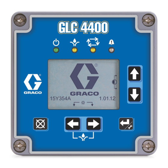
GLC 4400
Lubrication Controller
For controlling and monitoring single-line resistive, parallel, series progressive and dual
line, automatic lubrication systems. Not for use in explosive atmospheres!
Part No.: 24B591, Series E: DC Power
Part No.: 24B596, Series E: AC Power
Important Safety Instructions
Read all warnings and instructions in this
manual. Save these instructions.
313855K
EN
ti14059
Advertisement
Table of Contents

Subscribe to Our Youtube Channel
Related Manuals for Graco GLC 4400


Summary of Contents for Graco GLC 4400
- Page 1 Instructions GLC 4400 Lubrication Controller 313855K For controlling and monitoring single-line resistive, parallel, series progressive and dual line, automatic lubrication systems. Not for use in explosive atmospheres! Part No.: 24B591, Series E: DC Power Part No.: 24B596, Series E: AC Power...
- Page 2 Warnings Warnings The following warnings are for the setup, use, grounding, maintenance, and repair of this equipment. The exclama- tion point symbol alerts you to a general warning and the hazard symbol refers to procedure-specific risk. Refer back to these warnings. Additional, product-specific warnings may be found throughout the body of this manual where applicable.
- Page 3 Component Identification Component Identification Keypad, Display, and Icons Run Mode Functions Keypad Icons NOTE: Keypad Icons are described on Icon’s page 4. Direction Arrows ENTER Key: Press and hold for 3 seconds. Allows Up and Down Arrow Keys: Adjusts contrast. access to setup.
- Page 4 Component Identification Icon Definitions The following icons are used throughout this instruction manual and on the Controller’s Run and Setup Screens. Refer to this table if you are unsure of an Icon’s meaning. Power on indicator*. When power is supplied to the Lubrication Controller, Green LED illuminates under Function Icon located above display screen.
- Page 5 Installation Installation Typical Installation The installation shown in F . 2 is only a guide for selecting and installing system components. Contact your Graco distributor for assistance in planning a system to suit your needs. Controller Capabilities Low Reservoir Level...
- Page 6 Installation Installing the Lubrication Controller #6 screws (not provided) to secure junction box to mounting surface. AUTOMATIC SYSTEM ACTIVATION HAZARD Unexpected activation of the system could result in seri- ous injury, including skin injection and amputation. This device has an automatic timer that activates the pump lubrication system when power is connected or when exiting the programming function.
- Page 7 Installation System Configuration and Wiring The System Configuration Diagrams (F . 5 - F . 7), Table 3: Modes of Operation Sensor Wiring Diagrams (F . 8 - F . 10) and Wiring Diagrams (F . 11 - F . 16) on the following pages, show typical Injector, Divider Valve and Dual Line lubri- Mode Power...
- Page 8 System Configuration Divider Valve System Master Divider Valve Cycle Switch Pump Secondary Divider Valves Reservoir Low Level Switch Machine Count Switch Remote GLC 4400 Manual Run Pump On/Off External External O.K. Alarm External Cycle Low Level Machine Alarm Count 313855K...
- Page 9 Installation Dual Line System Lubrication Points Cycle Switch Reverser Bi-flo Valves Vent Line Machine Pump Count Swtich Reservoir Low Level Switch GLC 4400 Remote Pump On/Off Manual Run External External O.K. Alarm External Cycle Low Level Machine Alarm Count 313855K...
- Page 10 Installation Injector System Lubrication Points Injectors Pressure Switch Vent Line Machine Count Switch Pump Reservoir Low Level Switch Pump On/Off GLC 4400 Remote Manual Run External External O.K. Alarm External Cycle Low Level Machine Alarm Count 313855K...
- Page 11 Installation System Wiring NOTICE Do not connect any of the SW+ (13,9,5,1) and SW- (16,12,8,4) pins together, either directly or via a switch closure. Doing so will create a short circuit condition which will disable and potentially damage the controller. NOTE: •...
- Page 12 Installation Pump ON = Time; Pump OFF = Time 9 - 30VDC Ignition Switch 16 (SW-) 1(IN) 15 (SEN4) 2(COM) 14 (IN4) 13 (SW+) 9 - 30 VDC Battery 3(OUT1) 12 (SW-) 4(COM) 11 (SEN3) Air Solenoid 10 (IN3) 5(OUT2) 9 (SW+) 6(COM) 8 (SW-)
- Page 13 Installation System Wiring Pump ON = Cycle or Pressure; Pump OFF = Time 9 - 30VDC Ignition Switch 16 (SW-) 1(IN) 15 (SEN4) 2(COM) 14 (IN4) 13 (SW+) 9 - 30 VDC Battery 3(OUT1) 12 (SW-) 4(COM) 11 (SEN3) Air or Hydraulic Solenoid Pump Power or Motor 10 (IN3) 5(OUT2)
- Page 14 Installation System Wiring Pump ON = Cycle or Pressure; Pump OFF = Machine Count 9 - 30VDC Ignition Switch 16 (SW-) 1(IN) 15 (SEN4) 2(COM) 14 (IN4) 13 (SW+) 9 - 30 VDC Battery 3(OUT1) Dry Contact Switch 12 (SW-) 4(COM) 11 (SEN3) Air or Hydraulic Solenoid...
- Page 15 Installation System Wiring Options NOTICE Do not connect any of the SW+ (13,9,5,1) and SW- (16,12,8,4) pins together, either directly or via a switch closure. Doing so will create a short circuit condition which will disable and potentially damage the controller. All Units: Low Level Switch / External Manual Run / O.K.
- Page 16 Installation System Wiring Options: Alarm Out 9 - 30VDC 16 (SW-) 1(IN) 15 (SEN4) 2(COM) 14 (IN4) 13 (SW+) 3(OUT1) 12 (SW-) 4(COM) 11 (SEN3) 10 (IN3) 5(OUT2) 9 (SW+) Level 6(COM) 8 (SW-) 7(OUT3) 7 (SEN2) 1 A Fuse Alarm +9-30V Alarm 6 (IN2)
- Page 17 Application Programming Instructions Application Programming Instructions GLC4400 Single Line Parallel Programming Wiring Information Signal Signal J? +, - J? Pin# Pressure Power J7 1, 2 J6 2 Switch Pump Low Level J7 3, 4 J6 6 (opt) LL Alarm Remote Run J6 10 (opt) J7 5, 6 (opt) Machine Aux Alarm...
- Page 18 Application Programming Instructions GLC4400 Series Progressive Programming Wiring Information Signal Signal J? +, - J? Pin# Pressure Power J7 1, 2 J6 2 Switch Pump Low Level J7 3, 4 J6 6 (opt) LL Alarm Remote Run J6 10 (opt) J7 5, 6 (opt) Machine Aux Alarm...
- Page 19 Application Programming Instructions GLC4400 Time-Based Programming Wiring Information Signal Signal J? +, - J? Pin# Pressure Power J7 1, 2 J6 2 Switch Pump Low Level J7 3, 4 J6 6 (opt) LL Alarm Remote Run J6 10 (opt) J7 5, 6 (opt) Machine Aux Alarm J7 7, 8 (opt)
- Page 20 Setup Setup PIN Mode Enabled 1. To access Setup Mode, hold down the ENTER key for 3 seconds. The PIN ModeScreen shown in F See Electric Connection Warning, page 7. 21 displays. NOTE: When you first turn on power to the Lubrication Control- •...
- Page 21 Setup 8. If the PIN Code you entered is correct, the System Setup Screen, shown in F . 23 displays. 9. If the PIN Code you entered is incorrect, the digits flash. The Code must be re-entered by repeating steps 4 and 5. NOTE: •...
- Page 22 Setup Quick System Setup Defines when a lubrication event ends. PUMP ON Defines when a lubrication event begins. PUMP OFF Defines behavior of low level input. Typically used to signal controller when the Low Level lubrication level in the tank is low. Pressing CANCEL at any point will move to the previous subsection or the beginning of the previous section of the Quick System Setup.
- Page 23 Setup Use arrows to select mode icon (user can select both icons) PUMP OFF Mode Enter OFF/WAIT Time in HH:MM:SS by using the LEFT/RIGHT arrows to select digit and use the UP/DOWN arrows to change value. Sets time between lubrica- Timer tion events.
- Page 24 Setup Advanced System Setup TIMER Setup . 25 . 23 NOTE: Time is displayed in HH:MM:SS. 1. Use the UP/DOWN arrows to move the cursor up 1. Use the Arrow keys to move the cursor over the and down through the list of setup screens (F .
- Page 25 Setup PRESSURE Setup CYCLE END Setup . 27 . 26 NOTE: Time is displayed in HH:MM:SS. NOTE: Time is displayed in HH:MM:SS. 1. Use the Arrow keys to move the cursor over the 1. Use the Arrow keys to move the cursor over the PUMP ON time box.
- Page 26 Setup Cycle Mode Selection PUMP OFF Setup If the Cycle Mode is selected you will also be prompted Sets up how the PUMP OFF cycle is ended: Time, to set the desired number of cycles. Machine Count switch activation, or Machine Count acti- vations limited by a maximum time.
- Page 27 5. Press RESET. The Main Screen, page 24 displays. . 31 If BOTH is selected: If PUMP OFF is set to BOTH, the GLC 4400 will stay in 1. Use the Arrow keys to move the cursor over the the PUMP OFF state until the entered number of TIME field.
- Page 28 Setup 4. Use the RIGHT arrow to move the cursor to the next POWER UP Setup field. Repeat step 3. Define behavior of the controller during power ON. NOTE: The maximum number of Counts you can setup Default behavior is to continue program from point of in this field is 9999.
- Page 29 Setup 6. Press RESET. The Main Screen, page 24 displays. Third: At Power Up, immediately go to PUMP ON (normal on time).. Second: At Power Up, a delay occurs, the pump is off; then the normal lube cycle that was in process when power was removed, is resumed.
- Page 30 Setup 5. From the pull-down menu, select ON. PULSED Setup 6. Press ENTER. For systems requiring power to the pump to be turned on and off during a lubrication event, the user can utilize 7. Use the Arrow keys to move the cursor over the the pulse mode.
- Page 31 Setup Pulsed Pump Screen 10. Use the Arrow keys to move the cursor over the TIME ON field. 1. Use the Arrow keys to move the cursor over the PULSE pull-down menu. 11. Press ENTER. 2. Press ENTER. NOTE: The time is displayed in Seconds. 3.
- Page 32 Setup To enable PIN Code Entry: DISPLAY Setup Adjust setting related to the display and backlight. . 45 1. Use the Arrow keys to move the cursor over the PIN pull-down menu. . 47 2. Press ENTER. 1. Use the UP/DOWN Arrow keys to move the cursor over DISPLAY.
- Page 33 Setup 4. Use the Arrow keys to move the cursor over the Quick Cycle Screen Setup TIME ON field. The Quick Cycle screen setup is used to setup a Trou- bleshooting profile. . 49 . 51 NOTE: Time is displayed in HH:MM. 1.
- Page 34 Setup 12. Repeat steps 7 - 9 for the TIME OFF field. Low Level Filtering Screen Setup The Low Level Filtering screen setup is used to filter out 13. Use the Arrow keys to move the cursor over the spurious signals from rotating paddle type low level sen- pull-down menu.
- Page 35 Setup Sensor Field (Series E or later models only) 9. Repeat steps 7 and 8 until the desired time is dis- played. The SENSOR field identifies the behavior of the low 10. Press ENTER. level switch connected to the controller as Normally Open (NO) or Normally Closed (NC).
- Page 36 Run Mode Run Mode Screen Identification When you first turn the Lubrication Controller power on, the identification screen shown in F . 54 displays. The following screen is only shown as an example of the information that is displayed on a Run screen. A com- plete description of the icons and symbols shown in F 55 is provided on page 3.
- Page 37 NOTE: If Pump On is ended by a pressure switch and no Power Up delay is selected, when power to the GLC 4400 is turned on, the GLC 4400 starts at the beginning of the Pump On time instead of resuming the Pump On time where it left off.
- Page 38 If the Pump On sequence has been programmed to end by a Cycle Switch Activation: • The GLC 4400 pump output relay activates (J7-3) and will stay off until the time expires. (see Setup • The GLC 4400 pump output relay activates (J7-3) Menus, Pump Off, page 26).
- Page 39 If the Pump Off sequence has been programmed to be ended by MACHINE COUNTS with a maximum time: • The GLC 4400 pump output relay activates (J7-3) and will stay off until the correct number of counts • The GLC 4400 pump output relay activates (J7-3)
- Page 40 Run Mode Alarms Screen When a cycle alarm event occurs the Alarm Screen, shown in F . 63 displays. . 63 To clear an alarm, hold down the Clear Key on the dis- play Keypad (see page 3). The following is a list of other alarm events that may dis- play.
- Page 41 Troubleshooting Troubleshooting Description Problem Solution Power light off: Timer is not receiving power. Verify connections and verify power supply. No power supplied to solenoid Power light on: Verify solenoid con- Timer fails to activate solenoid nections Solenoid faulty Replace solenoid Timer faulty Replace timer Low level or other alarm...
- Page 42 Technical Data Technical Data Input Contact Power Source DC - model 24B591 9 - 30 VDC Power Source AC - model 24B596 100 VAC to 240 VAC - 50/60 Hz Power consumption 24 Watts Cycle Pressure Control Input (optional) Normally open pressure or cycle switch Machine Count Control Input (optional) Machine count control switch Lubrication level (optional)
- Page 43 Dimensions Dimensions Mounting Hole Layout 4.8 in. (122 mm) 3.23 in. (82.0 mm) 4.72 in. (120 mm) 3.58 in. (90.85 mm) 4.17 in. (105.92 mm) 313855K...
- Page 44 With the exception of any special, extended, or limited warranty published by Graco, Graco will, for a period of twelve months from the date of sale, repair or replace any part of the equipment determined by Graco to be defective.
Need help?
Do you have a question about the GLC 4400 and is the answer not in the manual?
Questions and answers
HOW TO ADJUST THE TIMER
To adjust the timer on the Graco GLC 4400:
1. Use the UP/DOWN arrows to navigate through the setup screens.
2. Move the cursor over the "PUMP ON time" box using the Arrow keys.
3. Press ENTER to select it.
4. Use the UP/DOWN arrows to set each digit (0–9) of the desired time (HH:MM:SS format).
5. Use the RIGHT arrow to move to the next digit.
6. Repeat steps 4 and 5 until the full time is set.
7. Move the cursor to the "ENDED BY" pull-down list.
8. Press ENTER and select "TIMER".
9. When done, press RESET to return to normal operation.
This answer is automatically generated