Graco 217314 Instructions-Parts List Manual
Stainless steel, waterbase compatible fluid pressure regulators
Hide thumbs
Also See for 217314:
- Instructions-parts list manual (24 pages) ,
- Instructions-parts list manual (16 pages) ,
- Instructions manual (18 pages)
Table of Contents
Advertisement
Quick Links
Instructions–Parts List
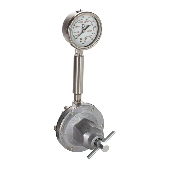
STAINLESS STEEL, WATERBASE COMPATIBLE
Fluid Pressure Regulators
Used to regulate fluid pressure in low pressure systems only.
Fluid Flow up to 3 GPM (11 liters/min)
Important Safety Instructions
Read all warnings and instructions in this manual.
Save these instructions.
See page 3 for List of Models and Table of Contents.
307212AK
Advertisement
Table of Contents

Related Manuals for Graco 217314


Summary of Contents for Graco 217314
- Page 1 Instructions–Parts List STAINLESS STEEL, WATERBASE COMPATIBLE Fluid Pressure Regulators 307212AK Used to regulate fluid pressure in low pressure systems only. Fluid Flow up to 3 GPM (11 liters/min) Important Safety Instructions Read all warnings and instructions in this manual. Save these instructions. See page 3 for List of Models and Table of Contents.
-
Page 2: Table Of Contents
........Graco Information . -
Page 3: Models
214706, 243414, 255374, and 24A082. Exposing this gauge to excessive pressure can damage the gauge, causing inaccurate readings and the needle will not return to zero. This damage is not covered by the Graco warranty. Air Operated Fluid Regulators Part No. - Page 4 Notes 307212...
-
Page 5: Warnings
D This equipment is for professional use only. D Read all the instruction manuals, tags, and labels before operating the equipment. D Use the equipment only for its intended purpose. If you are uncertain about usage, call your Graco distributor. -
Page 6: Installation
Installation FLUID SUPPLY Spring Operated Installation Models 214895, 214706, 243414, 217314, 221118, 255374, and 24A082 OUTLET BALL VALVE INLET BALL VALVE AIR FILTER & REGULATOR PIPE NIPPLES BACK PRESSURE VALVE FLUID RETURN Fig. 1 AIR REGULATOR BYPASS VALVE AIR SUPPLY... - Page 7 Installation Fluid pressure regulators are used for accurate, posi- Installing the Fluid Regulator tive control of the fluid pressure to spray guns, dis- pensing valves or atomizing heads. 1. Remove the temporary plumbing and install one regulator for each spray gun. See the Dimension- Regulators installed at circulating line take-offs or al Drawing on page 21 for regulator dimensions.
-
Page 8: Operation
Operation 2. Shut off the pump and relieve fluid pressure in the CAUTION system by triggering the gun and opening the back pressure regulator or other bypass valve. D The new system must be cleaned and tested thoroughly before admitting fluid to the regulator 3. - Page 9 Operation 7. Adjust the fluid regulator to the desired setting. NOTE: If using a fluid pressure gauge, reduce the regulator pressure before partially relieving pressure in a. Spring Operated Regulators Only (see Fig. 3). the gun hose, to ensure a correct gauge reading. Then The regulator can be adjusted in two ways: increase regulator pressure to the desired setting.
- Page 10 Notes 307212...
-
Page 11: Troubleshooting
Troubleshooting Before servicing this equipment always make sure to WARNING Relieve the Pressure. To reduce the risk of serious injury whenever you are instructed to relieve pressure, always follow the Check all possible remedies in the Troubleshooting Pressure Relief Procedure on page 8. Chart before disassembling the fluid regulator. -
Page 12: Service
Service Service of the Air Operated Regulators 10. Remove the spring (3), valve stem (9), and gasket (21) from the stem housing (18). WARNING 11. Thoroughly clean and inspect all parts. Replace any parts that appear to be worn or damaged. To reduce the risk of serious injury whenever you are instructed to relieve pressure, always follow the 12. - Page 13 Service Models 214980 (shown) & 244375 Air Bleed Hole Torque to 21–35 ft-lb (28–47 NSm) Torque to 21–25 ft-lb (28–34 NSm) Torque to 23–27 ft-lb (31–36 NSm) NOTE: Numbers indicate tightening sequence. Tighten evenly to 7–10 in-lb (0.8–1.1 NSm), then retorque to 125 in-lb (14 NSm) three times, consecu- tively, to compensate for diaphragm relaxation.
- Page 14 Service Service of the Spring Operated Regulators 10. Remove the diaphragm (25) – on Models 217314 and 221118 only, diaphragm (22), and gasket (26). WARNING 11. Remove the spring (3), valve stem (9) and gasket (21) from the stem housing.
- Page 15 Service Models 217314 and 221118 Torque to 21–25 ft-lb (28–34 NSm) Torque to 21–35 ft-lb (28–47 NSm) Torque to 23–27 ft-lb (31–36 NSm) PTFE side down toward housing (6) Models 214895, 214706, 243414, 255374, and 24A082 NOTE: Numbers indicate tightening sequence. Tighten evenly to 7–10 in-lb (0.8–1.1 NSm), then retorque...
-
Page 16: Parts
Parts Model 214895, Series H Without gauge. Includes items 1–26, 40 Model 214706, Series H With gauge. Includes items 1–40 Model 214706 only Ref. Part No. Description Qty. Part No. Description Qty. 100644 SCREW, soc hd cap; 176136 SCREW, adjustment 0.25”–20 x 0.75”... - Page 17 Parts Model 243414, Series B Model 255374, Series A Model 24A082, Series A ISO pitch thread inlet and outlet (not compatible with US standard pitch – fluid housing coated with PTFE based polymer) Includes items 1–40 TI0037 Ref. Part No. Description Qty.
- Page 18 Parts Model 217314, Series F With gauge. Includes items 1–32, 40 Model 221118, Series E Without gauge. Includes items 1–26, 32–40 Model 221118 only Model 217314 only Ref. Part No. Description Qty. Part No. Description Qty. 100644 SCREW, soc hd cap;...
- Page 19 Parts Model 214980 Series F Includes items 1–40 Ref. Part No. Description Qty. Part No. Description Qty. 100644 SCREW, soc hd cap; 112365*{ BALL; tungsten carbide 0.25”–20 x 0.75” 171867*{ GASKET 111736*{ SPRING, compression 171868*{ DIAPHRAGM; PTFE with 104319*{ O-RING, PTFE nylon fabric/Buna-N base 187880 HOUSING;...
- Page 20 Parts Model 244375 Series B Includes items 1–41 TI1697A Ref. Part No. Description Qty. Part No. Description Qty. 100644 SCREW, soc hd cap; 197213 STUD, mounting 0.25”–20 x 0.75” 112365*{ BALL; tungsten carbide 111736*{ SPRING, compression 171867*{ GASKET 104319*{ O-RING, PTFE 171868*{ DIAPHRAGM;...
-
Page 21: Dimensions
1/4 npt AIR INLET 3/8 npsm female INLET (Model 214980 only) (3/8–19, ISO male, Model 243414 only) 3.65” (93 mm) DIA. 3/8 npt(f) OUTLET (3/8–19, ISO female, Model 243414 only) 3/8 npsm female ADAPTER OUTLET (Models 217314 and 221118 only) 307212... -
Page 22: Technical Data
Maximum Fluid Inlet Pressure 250 psi (1.8 MPa, 18 bar) Regulated Fluid Pressure Range Models 217314 & 221118: 20–160 psi (0.15–1.1 MPa, 1.5–11 bar) Models 214706, 214895, 243414, 244375, 255374, & 24A082: 5–100 psi (30–700 kPa, 0.3–7.0 bar) Model 214980: 0–30 psi (0–210 kPa, 0–2 bar) Maximum Flow Capacity 3 gpm (11 liters/min) with 70 cps fluid at 200 psi (1.4 MPa, 14 bar) -
Page 23: Performance Charts
Performance Chart kPa bar MODELS 217314 250 PSI INLET, and 221118 1110 11.1 65 CPS 1040 10.4 250 PSI INLET, 600 CPS 250 PSI INLET, 65 CPS 100 PSI INLET, 65 CPS 250 PSI INLET, 65 CPS 100 PSI INLET,... -
Page 24: Warranty
With the exception of any special, extended, or limited warranty published by Graco, Graco will, for a period of twelve months from the date of sale, repair or replace any part of the equipment determined by Graco to be defective.
Need help?
Do you have a question about the 217314 and is the answer not in the manual?
Questions and answers