
Subscribe to Our Youtube Channel
Related Manuals for Tiso T1.1.BYO Series


Summary of Contents for Tiso T1.1.BYO Series
- Page 1 «TiSO-PRODUCTION» Company INDOOR SINGLE FULL-HEIGHT TURNSTILE Т1.1.BYO.ХХ OPERATION MANUAL AUIA.427-02 OM 2013...
-
Page 2: Table Of Contents
CONTENTS Page INTRODUCTION…….……………………….………………….……..….…..…. 1 DESCRIPTION AND OPERATION…..…………………………….…...……... 1.1 General Information and Designation…………..……………...…..….… 1.2 Specifications………………..……………………………...……..……… 1.3 Configuration and Completeness of Delivery.……….………….……..…..1.4 Design and Operation……………………………….…..….…………………. 1.5 Instrumentation, tools and accessories………….…..……………………..… 1.6 Marking………………………………………………………..…..….... 1.7 Packing…………………………………………………………….…..…..1.8 Description and operation of controller as component of the turnstile....2 INTENDED USE…………………………….…..…….......... -
Page 3: Introduction
This Operation Manual (hereinafter referred to as the OM), combined with certificate, covers the Indoor Single Full-Height Turnstile (hereinafter referred to as the turnstile). The Operation Manual contains information about design, specifications, installation, proper operation and maintenance of the turnstile. This Operation Manual is prepared in compliance with the specification requirements ТU U 31.6-31.6-32421280-003:2010. - Page 4 WARNINGS TO THE CUSTOMER ON SAFE OPERATION OF THE TURNSTILE These warnings are designed for ensuring of safety during operation of the turnstile to prevent violation of safety characteristics by improper installation or operation. These warnings are aimed at drawing attention of the customer to safety problems. GENERAL WARNINGS The Operation Manual is an integral part of the product and it should be handed over to the customer.
-
Page 5: Description And Operation
Designation: T1.1.BYO. Climatic version: Date of manufacture: _____________________ 20____ «TiSO-PRODUCTION» Company, Kiev Manufacturer: Serial Number: _____________________ 1.1.2 The turnstile is designed for pedestrian movement control at access points of industrial enterprises, banks, stadiums, administrative facilities etc. under actuation of control signals (coming from magnetic card readers, keypad etc.) of access control system or manually (from control panel). -
Page 6: Specifications
End of the Table 2 For climatic Operation conditions Parameter value version In enclosed spaces in the absence of Installation site direct impact of precipitations and solar radiation Vertical, deviation from vertical position Running position no more than 1º to any side is tolerated 1.1.5 Reliability indices: –... -
Page 7: Design And Operation
Table 4 Product Quantity, Name of product Notes designation/parameters piece Indoor Single Full-Height – T1.1.BYO._______ 1 kit Turnstile Components – Control panel AUIA.114.02.00.00 12V; Battery* Backup Power Supply 17А·h Turnstile installation kit Redibolt 12×110 М12 – (without frame) Spare parts, tools and accessories –... - Page 8 1 – bottom plate; 13 – roller; 2 – upper plate; 14 – spring; 3, 4 – ratchet gears; 15 – axis; 5, 6 – latches; 16 – damper; 7, 8 – springs; 17 – sprocket disk; 9, 10 – solenoids; 18 –...
-
Page 9: Instrumentation, Tools And Accessories
1.4.1.4 Electrical equipment of the turnstile, installed and located inside container, is designed for operation control of actuating mechanisms and LED display of the turnstile both as a part of access control system and by means of control panel. Electrical equipment of the turnstile includes: controller, power supply, battery, wired and distribution electrical accessories. -
Page 10: Packing
– index of protection; – serial number; – value of voltage, type of current, frequency and current consumption; – weight, kg; – marks of conformity to – date of manufacture; – inscription «MADE IN UKRAINE». Marking plate is located on fixed metalware of the turnstile. 1.6.2 Marking of transportation packing contains as follows: 1) Information inscriptions: –... - Page 11 5 light emitting diodes display state of the external connection inputs «INP1» ÷ «INP5»; the light emitting diode «POWER» displays existence of 5V power supply voltage; the light emitting diode «OPERATE» displays operating capacity of microprocessor; 7 light emitting diodes display state of the external connection outputs «OUT1» ÷ «OUT7»; 3 light emitting diodes «SENSOR»...
- Page 12 Table 5 Parameter description Parameter value Number of inputs for reception of control commands Number of signal outputs Type of inputs logical Type of outputs open collector Voltage of logical «1» (3 5)V Voltage of logical «0» (0 2,2)V Maximum peak voltage supplied to the inputs «INP1» ÷ «INP5» Peak voltage switched by transistors of signal output transistors Peak current switched through signal outputs 0,1А...
- Page 13 Delay of «WAITING FOR START OF ACCESS» is initiated. Controller energizes solenoid and thus unlocks rotor in the relevant direction. LED display corresponding to authorized access is switched from red to green. If during delay of «WAITING FOR START OF ACCESS» rotor rotation has started, then further behaviour of controller depends on the angle of rotor rotation: 6º...
- Page 14 From the position «AIRELOCK» rotor can’t be unlocked for exit in opposite direction by giving the command «RETURN» (active level of signal on the input «INP1») or by giving via RS-485 the command «FREE ACCESS» in opposite direction. The difference is that having received via RS-485 the command «FREE ACCESS»...
- Page 15 After rotor is turned to 6º in any side, the solenoid of opposite direction will be OFF, LED display will be switched to red and delay of «WAITING FOR START OF ACCESS» of opposite direction will be cancelled. Then controller is operating as it is described in the paragraph «SINGLE ACCESS IN ONE DIRECTION».
- Page 16 End of the Table 6 Connector/c Signal description and Description Direction Designation ontact No. parameters Signal is generated by OUT6 ХТ2/13 EXIT controller when fault of 5) active level of («ERROR») behaviour is detected signal (factory OUT7 Signal is generated by setting) –...
-
Page 17: Intended Use
End of the Table 6 Connector/c Signal description and Description Direction Designation ontact No. parameters 1) type of output – open collector; 2) peak voltage on ХТ4/31 - MGA EXIT Used for control of solenoids privacy key 50V; of rotor mechanism 3) peak current of public key 9A;... -
Page 18: Layout And Installation
2.2 Layout and installation 2.2.1 The turnstile and components of delivery kit are delivered to the installation site in the factory packing. The turnstile should be unpacked only on installation site. 2.2.2 Preparation of the turnstile for installation (dismounting) and commissioning should be performed according to this OM with mandatory observation of the safety measures specified in p. -
Page 19: Contingency Actions
Table 9 Operation Mode Mode Setting LED Display 1 Turnstile is closed in – both directions (initial Red LED display is lit state) Green arrow of single access is Push the «SINGLE» access button 2 Single access in one lit in chosen direction and red to access in selected direction direction LED display is lit in opposite... -
Page 20: Maintenance
3 MAINTENANCE 3.1 General instructions 3.1.1 Commissioning and subsequent maintenance of the turnstile should be performed only by the staff to be in charge of the turnstile. 3.1.2 The turnstile can be serviced only by the staff having the relevant electrical safety qualification level according to the national requirements. -
Page 21: Routine Maintenance
4 ROUTINE MAINTENANCE 4.1 General instructions Possible malfunctions of the turnstile listed in the Table 10 are remedied by the customer. More complicated malfunctions are remedied by manufacturer’s representative. ATTENTION: INSPECTION, CLEANING, REPAIR OF THE TURNSTILE’S COMPONENTS MUST BE PERFORMED ONLY AFTER DEENERGIZING OF THE TURNSTILE! 4.2 List of possible malfunctions List of possible malfunctions and their remedies are specified in the Table 10. -
Page 22: Transportation And Storage
The turnstile does not contain hazardous materials and special measures are not required during its utilization. 7 PACKING CERTIFICATE Т1.1.BYO. Single Full-Height Turnstile No. _____________________ Name of product Trademark Serial number «TiSO-PRODUCTION» Company is packed by Name or code of manufacturer according to requirements specified by applicable technical documentation. __________________________ _____________________ ___________________ Position Signature... -
Page 23: Acceptance Certificate
«TiSO-PRODUCTION» Company 72 Yamskaya str., 03680, Kiev, Ukraine Tel.: +38 (044) 461-79-69 Tel../Fax: +38 (044) 586-46-47 E-mail: export@tiso.ua, log1@tiso.ua www.tiso-turnstiles.com Our equipment complies with requirements of the European Standards: EN 60335-1:2002, EN 61000-6-1:2007; EN 61000-6-3:2007; EN 61000-4-2:2009; EN 61000-4-3:2006; EN 61000-4-4:2004; EN 61000-4-5:2006; EN 61000-4-11:2004 and is in conformity with requirements of the following EC Directives: 2004/108/EC;... - Page 24 WARRANTY COUPON No. 1 To be completed by Manufacturer Indoor Single Full-Height Turnstile (reference designation) Serial number Date of manufacture (Year, Month, Date) Representative of the manufacturer’s Quality Control Department Place of Seal (Signature) (Full name) Address for product quality reclamation 72 Yamskaya str., 03680, Kiev, Ukraine Tel.: +38 (044) 461-79-69, Tel./Fax: +38 (044) 586-46-47 To be completed by Seller’s representative...
-
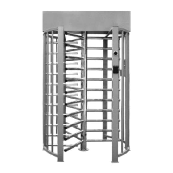
Page 25: Single Full-Height Turnstile T1.1.Byo.xх
Appendix А (mandatory) Design, overall and installation dimensions of the Indoor Single Full-Height Turnstile 1 – container; 2 – passage wall; 3 – enclosure wall; 4 – rotor Figure А.1– Turnstile Т1.1.BYO.ХХ АUIА.427.00.00.00-02 OM... -
Page 26: Appendix B (Mandatory) Control Panel And Connection Diagram
Appendix B (mandatory) Control panel and connection diagram 1 – housing; 5 – «FREE ACCESS» mode control button; 2 – «SINGLE ACCESS» mode control button; 6 – «PANIC» mode control button; 3 – front plate; 7 – access direction LED display; 4 –... - Page 27 Appendix B (continued) Control panel and connection diagram Figure B.2 – Connection diagram of the control panel AUIA.114.02.00.00 АUIА.427.00.00.00-02 OM...
-
Page 28: Appendix C (Mandatory) Wiring Diagram Of The Turnstile T1.1.Byo.xх
Appendix C (continued) Wiring Diagram of the turnstile Figure C.1 – Wiring Diagram of the Turnstile АUIА.427.00.00.00-02 OM...
Need help?
Do you have a question about the T1.1.BYO Series and is the answer not in the manual?
Questions and answers