
Related Manuals for Tiso T3.РKС.XC


Summary of Contents for Tiso T3.РKС.XC
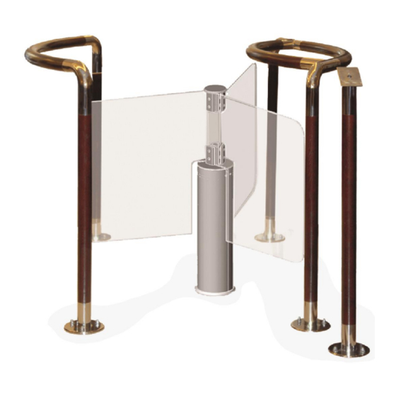
- Page 1 «TiSO-PRODUCTION» Company SERVO-OPERATED ROTOR TURNSTILE T3.РKС.XC OPERATION MANUAL AUIA.123-05 OM 2013...
-
Page 2: Table Of Contents
CONTENTS Page INTRODUCTION…….……………………….……………………….……..….……. 1 DESCRIPTION AND OPERATION…..…………………………….…...……....1.1 General Information and Designation…………..……………...…..…..… 1.2 Specifications………………..……………………………...……..……..….. 1.3 Configuration and Completeness of Delivery.……….………….……..…..1.4 Design and Operation……………………………….…..….…………………..1.5 Instrumentation, tools and accessories………….…..………………………..1.6 Marking………………………………………………………..…..…....1.7 Packing…………………………………………………………….…..…..1.8 Description and operation of controller as component of the turnstile....2 INTENDED USE…………………………….…..……............ -
Page 3: Introduction
INTRODUCTION This Operation Manual (hereinafter referred to as the OM), combined with datasheet, covers the servo- operated waist-high rotor turnstile (hereinafter referred to as the turnstile). The Operation Manual contains information about design, specifications, installation, proper operation and maintenance of the turnstile. - Page 4 WARNINGS TO THE CUSTOMER ON SAFE OPERATION OF THE TURNSTILE These warnings are designed for ensuring of safety during operation of the turnstile to prevent violation of safety characteristics by improper installation or operation. These warnings are aimed at drawing attention of the customer to safety problems. GENERAL WARNINGS Safety measures and requirements specified in this in this OM must be observed: the turnstile must be connected to ground loop prior to operation;...
-
Page 5: Description And Operation
1 DESCRIPTION AND OPERATION 1.1 General Information and Designation 1.1.1 Name of product: Rotor waist-high turnstile Climatic version: 1.1.2 The turnstile is designed for pedestrian movement control during tight access control at access points of industrial enterprises, banks, stadiums, administrative facilities etc. under actuation of control signals (from magnetic card readers, keypad etc.) of access control system or manually (from manual control panel). -
Page 6: Configuration And Completeness Of Delivery
Table 3 Parameter description Unit measure Parameter value Traffic flow capacity in free access mode is at least man/min. Traffic flow capacity in single access mode is at least man/min. Max. passageway width Supply voltage: 100 240 – AC power supply (primary) ~ 50/60 –... -
Page 7: Design And Operation
Redibolt 92F112A4-0 – (12×140 М10) Mounting kit Redibolt 92F110A2-0 – (10×120 М8) Reader rack*: – with LED display panel** AUIA.121.04.00.00.00.01(-06) Modification of rack is defined by the order – without LED display AUIA.121.04.00.00.00 panel – Certificate AUIA.123-05 PS – – Packing * Optional ** LED display operation on the reader racks AUIA.121.04.00.00.00-01(-06) is described further in... -
Page 8: Instrumentation, Tools And Accessories
1.4.2.4 12V DC power voltage is provided by power supply unit. 1.4.2.5 The turnstile’s wiring diagram is shown in the Appendix C. 1 – glass blades; 5 – Redibolt; 2 – cup with drive; 6 – screws М4х10; 3 – sheeting; 7 –... -
Page 9: Packing
– gross weight in kg; – net weight in kg; – volume of package in cubic meters; 2) Handling marks: – «Fragile. Handle with Care»; – «Keep dry»; – «Centre of gravity»; – «Top». 1.6.3 Shipping documentation is packed with bag from polyethylene film. Marking is applied on insert from cardboard or paper. - Page 10 Controller supply voltage (10 27)V Consumption current when outputs «MOT1» and «МОТ2» are OFF ≤0,15 А Climatic modification and placement category of according to the GOST 15150-69 Appearance of the controller is shown in the Figure 2. 70 mm 60 mm X3.1 X3.5 O4 mm...
- Page 11 X1/12 +5 V EXIT Not applicable X2/1 GRN1 EXIT Not applicable X2/2 RED1 EXIT Not applicable X2/3 GRN2 EXIT Not applicable X2/4 RED2 EXIT Not applicable 1) type of output – open collector; 2) peak voltage on privacy X2/5 -MG1 EXIT Not applicable key –...
- Page 12 Voltage of logical «1» (3 5)V Voltage of logical «0» (0 2,2)V Maximum peak voltage supplied to the inputs «INP1» ÷ «INP5» Peak voltage switched by transistors of signal outputs 0,1А Peak current switched through signal outputs Power supply voltage of controller (9 15)V Peak consumption current 0,15А...
- Page 13 «SINGLE ACCESS IN ONE DIRECTION»; «FREE ACCESS IN ONE DIRECTION»; «LOCKING OF ACCESS». Other operating modes are combinations of various or similar modes in different directions: Single access in one direction and any mode in opposite direction. Free access in one direction and any mode in opposite direction. Locking of access in one direction and any mode in opposite direction.
- Page 14 Controller is switched to this mode in two cases: first: when the «OPEN А/В» (input «INP4» or «INP5») command is kept in active status at the moment of crossing by rotor the point 120º at the termination of «SINGLE ACCESS»; second: after reception of the «FREE ACCESS»...
- Page 15 ХТ2/1 GND (common) OUT1 ХТ2/2 («START OF EXIT Signal is generated by ACCESS А») controller when rotor is rotated from 6º to 54º in OUT2 1) type of output – ХТ2/3 («START OF the appropriate direction EXIT open collector; ACCESS В») 2) peak voltage on OUT3 privacy key 55V;...
-
Page 16: Intended Use
1) type of output – open collector; 2) peak voltage on ХТ4/1 - MGA EXIT privacy key 50V; Not applicable 3) peak current of public key 9A; 4) resistance of public ХТ4/3 - MGB EXIT key 0,11Ohm ХТ4/2 + MGA Not applicable ХТ4/4 + MGB... -
Page 17: Preparation For Use
2.2.3 The turnstile is installed in the following order: – inspect the turnstile for integrity, absence of visual damages and defects; – verify the turnstile’s completeness; – prepare installation site for mounting of ready-to-install turnstile: surface should be plain, hard and without defects (corrugations, overlaps etc.);... - Page 18 independently. Repeat the check for opposite direction Green arrow of free Make sure that at each push in Push the «FREE» access in chosen the direction of free access access button to rotor rotates to 120º and stops. 4 Free access in one direction is blinking access in the direction...
-
Page 19: Contingency Actions
In this case other control panel buttons of single and free access in chosen direction are locked ** In this case all control panel buttons of single and free access in both directions are locked 2.3.2.3 The turnstile is ready for long-term operation. 2.4 Contingency actions For emergency evacuation of people (in case of fire, acts of God etc.) and providing of free access the turnstile must be unlocked from control panel by sending the relevant command. -
Page 20: Routine Maintenance
4 ROUTINE MAINTENANCE 4.1 General instructions Possible malfunctions of the turnstile are listed in the Table 10 and are remedied by customer. More complicated malfunctions are remedied by manufacturer’s representative. ATTENTION: INSPECTION, CLEANING, REPAIR OF THE TURNSTILE’S COMPONENTS MUST BE PERFORMED ONLY AFTER DEENERGIZING OF THE TURNSTILE! 4.2 List of possible malfunctions List of possible malfunctions of the turnstile and their remedies are specified in th e Table... -
Page 21: Manufacturer's Warranty And Conditions Of Intermediate Maintenance
«TiSO-PRODUCTION» Company 72 Yamskaya str., 03680, Kiev, Ukraine Tel.: +38 (044) 461-79-69 Tel../Fax: +38 (044) 586-46-47 E-mail: export@tiso.ua, log1@tiso.ua www.tiso-turnstiles.com Our equipment complies with requirements of the European Standards: EN ISO 12100:2010; EN 614-1:2006+A1:2009; EN 1037:1995+A1:2008; EN 60204-1:2006; EN 953:1997+A1:2009; ISO 3864:1995; EN ISO 13857:2008; EN ISO 13849-1:2006; EN 1088:1995; EN... -
Page 22: Appendix А Design, Overall And Installation Dimensions Of The Rotor Turnstile
Appendix А Design, overall and installation dimensions of the rotor turnstile 1 – central enclosure; 3 – servo-operated turnstile; 2 – side enclosure; 4 – reader racks Figure А.1 – Installation of the rotor turnstile AUIA.123.00.00.00.00-05 OM... -
Page 23: Appendix B Control Panel And Connection Diagram
Appendix B Control panel and connection diagram 1 – housing; 5 – «FREE ACCESS» mode control button 2 – «SINGLE ACCESS» mode control button 6 – «PANIC» mode control button; 3 – front plate; 7 – access direction LED display; 4 –... - Page 24 Appendix B (continued) Control panel and connection diagram Figure B.2 – Connection diagram of the control panel AUIA.114.02.00.00 AUIA.123.00.00.00.00-05 OM...
-
Page 25: Appendix C Wiring Diagram Of The Turnstile T3.Ркc.xc
Appendix C Wiring diagram of the turnstile Figure C.1 – Wiring diagram of the rotor turnstile T3.РОC.XC AUIA.123.00.00.00.00-05 OM...
Need help?
Do you have a question about the T3.РKС.XC and is the answer not in the manual?
Questions and answers