
Related Manuals for Tiso CENTURION-M TWIN


Summary of Contents for Tiso CENTURION-M TWIN
- Page 1 “TiSO-PRODUCTION” LTD SERVO-OPERATED TRIPOD TURNSTILE CENTURION-M TWIN BASTION-M TWIN TWIX-M TWIN OPERATION MANUAL 2019...
-
Page 2: Table Of Contents
CONTENTS INTRODUCTION ............................3 WARNINGS TO THE CUSTOMER ......................4 ON SAFE OPERATION OF THE TURNSTILE ..................4 1. DESCRIPTION AND OPERATION ......................5 1.1. General Information and Purpose....................5 1.2 Specifications ........................... 6 1.3 Configuration and Scope of Delivery ....................6 1.4 Design and operation ........................ -
Page 3: Introduction
INTRODUCTION This Operation Manual (hereinafter referred to as OM) covers the servo-operated turnstile (hereinafter referred to as the "turnstile"). The Operation Manual contains information about design, specifications, installation for proper operation and maintenance of the turnstile. This Operation Manual is prepared in compliance with the specification requirements ТУ У... -
Page 4: Warnings To The Customer
WARNINGS TO THE CUSTOMER ON SAFE OPERATION OF THE TURNSTILE These warnings are designed for ensuring of safety during operation of the turnstile to prevent violation of safety characteristics by improper installation or operation. These warnings are aimed at drawing attention of the customer to safety problems. GENERAL WARNINGS The Operation Manual is an integral part of the product and it shall be handed over to the customer. -
Page 5: Description And Operation
1. DESCRIPTION AND OPERATION 1.1. General Information and Purpose. 1.1.1 Turnstile purpose: The turnstile is designed for arrangement of individual pedestrian access at access points of industrial enterprises, banks, stadiums, administrative facilities etc. driven by control signals of access control system (from keypad, proximity card readers) or manually (from wire control panel). -
Page 6: Specifications
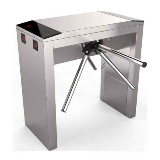
1.1.4 Reliability indices: mean time to repair (without delivery time of spare parts, tools and accessories) – at most 6 hours; mean time to failure – at least 1 500 000 accesses; mean service life between overhauls – at least 10 years 1.2 Specifications Key parameters of the turnstile are specified in Table 4 Table 4... - Page 7 T3.TCC.КE.X); The turnstile basic modification is made of brushed stainless steel CENTURION-M TWIN BASTION-M TWIN TWIX-M TWIN 1 - turnstile rack; 6 - hub; 2 - LED display; 7 - barrier rod; 3 - card reader location; 8 - lock door;...
- Page 8 Battery (capacity 4 Ah) For convenience of delivery the turnstile is supplied ready-to-install with dismounted barrier rods. (fig.2). 1.3.3 The turnstile design, overall and installation dimensions (Fig.3) Fig. 3 - Tripod turnstile dimensions Is not included in the turnstile scope of delivery - to be equipped by the customer, if appropriate...
-
Page 9: Design And Operation
230 V network and control panel are mounted, are fixed inside the turnstile post 1 (See Fig.1) under the removable door 8 (for the turnstiles CENTURION-M TWIN and BASTION-M TWIN) or removable lid 4 (for the turnstiles TWIX-M TWIN). Controller controls the turnstile motor analyzing signals from speed and position sensors as well as provides the motor protection against overloads. - Page 10 1.4.1.3 The tripod turnstile control mechanism design is shown in Figure 5. 1 – gear motor; 6 – hub shaft;; 2 – position sensor; 7 – mechanism body; 3 – antipanic device; 8 – hub with barrier rods; 4 – locking solenoid; 9 –...
- Page 11 3) free access in the direction “A” or “B”; 4) "PANIC" mode; 1.4.3.2 In the initial state, when the turnstile is deenergized, barrier rods are locked from rotation and access is barred. 1.4.3.3 Green arrow in the intended direction is lit on LED display and barrier rods are unlocked when access permission command in the direction “A”...
-
Page 12: Instrumentation, Tools And Accessories
а) The positions of the rod in the b) The positions of the restored rod "PANIC" mode before restoring in the "Standby"mode Fig.7 - Deactivation of the "PANICA" mode and restoration of the leash to the starting position More detailed description of the turnstile operation modes is given in section 1.8 "Description and operation of controller as a component of the turnstile”». -
Page 13: Description And Operation Of Controllers As Components Of The Turnstile
1.6 Description and operation of controllers as components of the turnstile 1.6.1 Motorized mechanism controller РСВ.201.01.00.00 The controller is designed for acquisition of commands from external control devices (control panel, access control system etc.) and generation of control signals for swing gate motorized mechanism 1.6.1.1 The controller is assembled on the (85 х... - Page 14 Fig. 7– Appearance of the motorized mechanism controller PCB.201.00.00 1.6.1.3 Description of controller operation The controller controls the turnstile DC motor and the turnstile mechanism locking solenoids according to the logic entered into program depending on incoming commands, rotor position, rotation speed and motor current. It provides rotor locking in initial state, maintaining rotor rotation speed in access mode as well as motor protection in emergency situations.
- Page 15 Table 6 Connector Designati Signal parameters and Direction / contact Purpose description Not applicable X1/1 ENTRY 1) logical «0» (0 1,7) V; Not applicable X1/2 ENTRY 2) logical «1» (3,7 5) X1/3 ENTRY Selection of turnstile type Not applicable X1/4 ENTRY 3) active level of signal –...
- Page 16 • LEDs «RX» and «TX» initiate respectively reception and transmittance in serial port. 40 terminals are installed on the board: 14 of them are designed for external connections, the rest are designed for connection to the turnstile units or are standby 1.6.2.2 Technical features The controller technical features are shown in Table 7.
- Page 17 Fig. 8 – Appearance of the turnstile controller РСВ.112.21.20.00 1.6.2.3.2 «SINGLE ACCESS IN ONE DIRECTION» In this mode the controller unlocks rotor through solenoid in one direction with the possibility of revolving to 120º. It enables access of one pedestrian through the turnstile. The controller is switched to “SINGLE ACCESS IN ONE DIRECTION”, if in the INITIAL STATE it receives “TO BE OPENED А/В"...
- Page 18 Then two alternatives of events are possible. 1) First alternative: If within active status of "TO BE OPENED /В" (“INP4”/“INP5”) or during delay of WAITING FOR START OF ACCESS rotation of rotor is not started, then controller is reset to ”INITIAL STATE”; 2) Second alternative: If in the above mentioned cases rotation of rotor is started, then further behavior of controller depends on angle of rotor rotation.
- Page 19 3)Initiates two delays of "WAITING FOR START OF ACCESS А and В" for each access individually, which are counted from the moment of acquisition of commands. 4) The controller is waiting for start of access. 5) After rotor is revolved to 6º in any side, opposite direction will be locked LED is switched to red.
- Page 20 Continued Table 8 "TO BE OPENED FOR SINGLE/FREE ACCESS" INP4 ХТ1/4 (« TO BE OPENED command. Input is activated ENTRY A») within the time of holding in active state. Free access is occurred when entry is kept INP5 in active state after rotor ХТ1/5 («...
- Page 21 Continued Table 8 1) Type of output - ХТ3/8 INDAR EXIT open collector 2) Peak voltage on ХТ3/9 INDAG EXIT It is used for the turnstile privacy key 30 V LED display control 3) Peak current of ХТ3/10 INDBR EXIT public key 2A 4) Resistance of ХТ3/11...
-
Page 22: Intended Use
2 INTENDED USE 2.1 Operation limitations 2.1.1 The turnstile must be used in the environment specified in p. 1.1.5 of this document subject to the specifications listed in section 1.2. IT IS FORBIDDEN: 1) TO MISUSE THE TURNSTILE (See section 1 "DESCRIPTION AND OPERATION");... - Page 23 Connection of all cables to be performed only when power supply is OFF; Cables to be laid in compliance with electric code; The turnstile to be installed by at least 2 installers. 2.2.4 General layout of the turnstile access ways а) TWIX-М...
- Page 24 7) Installation of hub on the tripod turnstile (Through the example of the turnstile AUIA.095-10-X2 " CENTURION-M TWIN"). (For the sake of convenience installation of the hub with barrier rods is acceptable at the end of installation and connection of the turnstile): а) The hub (1) barrier rods (2) to be set out manually (See Fig.
- Page 25 Fig. 14 – Installation of the hub with barrier rods into the tripod turnstile body 8) The rack door to be removed by turning the lock key (Fig.15) to access to the " «CENTURION-M TWIN » and «BASTION-M TWIN » tripod turnstile base fixation and service holes as well as terminal blocks.
- Page 26 5.To secured with anchors. 5 – General view of the " CENTURION-M TWIN" and "BASTION-M TWIN" tripod turnstiles assembly 9) Two turnstile rack doors to be removed by unscrewing one screw fastening door to the body to access to the "TWIX-M TWIN"...
- Page 27 Proximity card readers , to be installed if access control system (ACS) is available: In the turnstiles «CENTURION-M TWIN», «TWIX-M TWIN» и «BASTION-M TWIN» card readers are installed on special and height adjustable bracket, which is located under upper lid 4 next to LED display 3 (Fig. 19).
-
Page 28: Preparation For Use
WARNING: During the turnstile installation it should be taken into account that horizontally positioned barrier rod must be at a distance not more than (50 ÷ 100) mm from access way creator (any surface perpendicular to horizontally positioned barrier rod: enclosure module, wall, etc.). 2.3 Preparation for use 2.3.1 Commission guidelines Prior to the turnstile energization:... -
Page 29: Contingency Actions
Continued Table 9 FREE button to be pushed for Green arrow of authorized free access is 8. Free access in one access in selected direction ("A" lit in selected direction and red LED of direction and locking access or "B") and LOCK button to be locked access is blinking in opposite in opposite direction pushed for blocking access in... -
Page 30: Safety Measures
3.2 Safety Measures 3.2.1 During maintenance of the turnstile the relevant safety measures according to p. 2.1 to be observed. IT IS FORBIDDEN: DEFECTIVE APPLIANCES, TOOLS, FUSES, INSTRUMENTATION THE SERVISE LIFE OF WHICH EXPIRED. 3.2.2 When instrumentations are prepared for operation it is necessary to strictly comply with the safety requirements specified in instrumentation instruction manuals. -
Page 31: Routine Maintenance
lubrication of all rubbing stop levers, wheel and pinion teeth of the turnstile control mechanism at least monthly with lubricant OKB-122-7 according to GOST 18179- 72 or LITOL 24, Ciatim or engine oil. Table 11 - Periodic maintenance by technical staff Component Period Action... - Page 32 Continued Table 12 Check lock is operating Check connections and No communication between movement of lock controllers(boards) Check the communication Rotor(arms) does not The sensor of position is set wires between rotate wrong controllers(boards) The sensor of position is Setup the sensor of position or faulty change PCB Investigate lock fault...
-
Page 33: Post Repair Checkout
Continued Table 12 Check by hand if they work or Jamming in the mechanism Rotor gets stuck The sensor of position is set Check the mechanism parts intermittently during wrong Setup the sensor of position or rotation The PCB.201.01.00.00 is change PCB faulty Check the wires... -
Page 34: Disposal
turnstile to be kept indoor with normal climatic conditions without original packing within 12 hours before commissioning: ambient temperature: + 15°С to +35°С; relative humidity: 45% to 80 %; atmospheric pressure: 84,0 to 106,7kPa (630-800 mm Hg). 6 DISPOSAL The turnstile design does not contain materials environmentally hostile and hazardous to human health and special measures are not required for its disposal. - Page 35 "TiSO-PRODUCTION" LTD 14 Promyshlennaya str., 02088 Kiev, Ukraine Tel.: +38 (044) 291-21-11 Tel../Fax: +38 (044) 291-21-02 E-mail: sales@tiso.global www.tiso.global SERVICE CENTER e-mail: service1@tiso.global Our equipment complies with requirements of the European Standards: EN ISO 12100:2010; EN 614-1:2006+A1:2009; EN 1037:1995+A1:2008; EN 60204-1:2006;...
-
Page 36: Annex А Design, Overall And Installation Dimensions Of The " Сenturion-М Twin " Type Turnstile
Annex А (mandatory) Design, overall and installation dimensions of the "СENTURION-М TWIN" type turnstile Figure А.1 – Tripod turnstile " CENTURION-M TWIN "... -
Page 37: Continued Annex А Design, Overall And Installation Dimensions Of The Turnstile "Bastion-M Twin
Continued Annex А (mandatory) Design, overall and installation dimensions of the turnstile «BASTION-M TWIN» Figure А.2 – Tripod turnstile “BASTION-M TWIN”... -
Page 38: Continued Annex А Design, Overall And Installation Dimensions Of The Turnstile "Twix-M Twin
Continued Annex А (mandatory) Design, overall and installation dimensions of the turnstile «TWIX-M TWIN» Figure А.3 – Tripod turnstile “TWIX-M TWIN”... -
Page 39: Annex B Control Panel And Connection Diagram
Annex B (mandatory) Control panel and connection diagram 1 – control panel housing; 5 – "FREE ACCESS" mode control button; 2 – "SINGLE ACCESS" mode control button 6 – "PANIC" mode control button; 3 – front plate; 7 – access direction LED display; 8 –... - Page 40 Continued Annex B Control panel and connection diagram Figure B.2 – Control panel AUIA.114.02.00.00 connection diagram...
-
Page 41: Annex C Servo-Operated Tripod Turnstile Wiring Diagram
Annex C (mandatory) Servo-operated tripod turnstile wiring diagram CONTROL MECHANISM Control panel AUIA195 A UIA195 XP1 PCB +12V CONTROLLER SPEED CONTROLLER PCB 112.21.20.00 PCB 201.01.00.00 ANGLE 1 ANGLE 2 INP 1 OPTO 1 PANIC ZERO 3 INP 2 OPTO 2 IN 1 GRN 1 OPEN "A"... -
Page 42: Annex D.1 Wiring Diagram Of The Turnstile Connection To Access Control System (Acs) In Pulse Mode
Annex D.1 (mandatory) Wiring diagram of the turnstile connection to access control system (ACS) in pulse mode Figure D.1 – Wiring diagram of the turnstile connection to ACS... -
Page 43: Annex D.2 Wiring Diagram Of The Turnstile Connection To Access Control System (Acs) In Hold Mode
Annex D.2 (mandatory) Wiring diagram of the turnstile connection to access control system (ACS) in hold mode Figure D.2 – Wiring diagram of the turnstile connection to ACS... -
Page 44: Annex D.3 Wiring Diagram Of The Turnstile Connection To Fire Alarm System (Fas)
Annex D.3 (mandatory) Wiring diagram of the turnstile connection to fire alarm system (FAS) Figure D.3 – Wiring diagram of the turnstile connection to fire alarm system (FAS) -
Page 45: Annex D.4 Wiring Diagram Of The Turnstile Connection To Fire Alarm System (Fas)
Annex D.4 (mandatory) Wiring diagram of the turnstile connection to fire alarm system (FAS) Figure D.4 – Wiring diagram of the turnstile connection to fire alarm system (FAS) -
Page 46: Annex D.5 Wiring Diagram Of The Turnstile Connection To Control Panel
Annex D.5 (mandatory) Wiring diagram of the turnstile connection to control panel Figure D.5 – Wiring diagram of the turnstile connection to control panel...
Need help?
Do you have a question about the CENTURION-M TWIN and is the answer not in the manual?
Questions and answers