
Related Manuals for Tiso STAR-TS T3.POH.XC Series


Summary of Contents for Tiso STAR-TS T3.POH.XC Series
- Page 1 “TiSO-PRODUCTION” LTD SERVO-OPERATED ROTOR TURNSTILE «STAR-TS» T3.РОH.XC «STAR-GS» T3.РОC.XC OPERATION MANUAL AUIA.123 OM (rev.1.4) UKRAINE 2023...
-
Page 2: Table Of Contents
CONTENTS INTRODUCTION ............................3 1. DESCRIPTION AND OPERATION ..................... 5 1.1 General Information and Purpose ......................5 1.2 Specifications ............................6 1.3 Configuration and Scope of Delivery ....................6 1.4 Design and operation ..........................7 1.5 Instrumentation, tools and accessories ....................10 1.6 Description and operation of controllers as component of the turnstile .......... -
Page 3: Introduction
INTRODUCTION This Operation Manual (hereinafter referred to as the OM), combined with certificate, covers the servo-operated rotor waist-high turnstile (hereinafter referred to as the turnstile). The Operation Manual contains information about design, specifications, installation, proper operation and maintenance of the turnstile. - Page 4 WARNINGS TO THE CUSTOMER ON SAFE OPERATION OF THE TURNSTILE These warnings are designed for ensuring of safety during operation of the turnstile to prevent violation of safety characteristics by improper installation or operation. These warnings are aimed at drawing attention of the customer to safety problems GENERAL WARNINGS The Operation Manual is an integral part of the product and it shall be handed over to the customer.
-
Page 5: Description And Operation
1. DESCRIPTION AND OPERATION 1.1 General Information and Purpose 1.1.1 Turnstile purpose: The rotary turnstile is designed for arrangement of individual pedestrian access at access points of industrial enterprises, banks, stadiums, administrative facilities etc. driven by control signals of access control system (from keypad, proximity card readers) or manually (from wire control panel). -
Page 6: Specifications
1.1.3 The operation condition parameters according to GOST 15150-69 are specified in Table 2 Table 2 - For climatic modification NF4. Operation conditions Parameter value +1°С to +40°С Ambient air temperature 80 % at 20 ºС (without condensation) Relative air humidity Ambient air allowable pressure 84 to 106,7 kPa - 40 °С... -
Page 7: Design And Operation
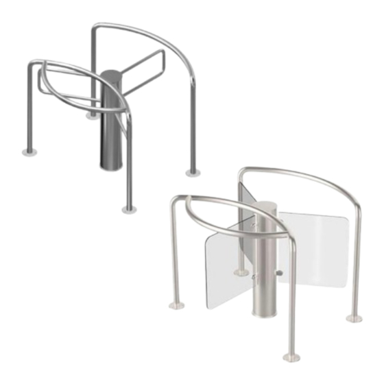
The turnstile basic modification is with brushed stainless steel body (reference designation T3.РОX.SС. a)« Star-TS» b) «Star-GS Legend: 1. Side enclosure; Top lid; 2. Central enclosure; The base with the rack of the 3. Housing; turnstile is mechanism 4. Stainless steel P-shape leaf (3 pcs) or glass leaf (3 pcs); assembled;... - Page 8 1.4.1.6 The control panel is made as a small desktop device in plastic case and is designed for setting and display of operation modes when the turnstile is operated manually. The control panel and its connection diagram are shown in Annex C. a)«...
- Page 9 b) «Star-GS» Legend: 1. – Side enclosure; 10 – Сontroller PCB.201.01.00.00 of the mechanism – Central enclosure; control; – Housing; 11 – Сontroller PCB.112.21.20.01 of the turnstile 4. – Glass leaf (3 pcs); control; – Top lid with screw М12; 12 –...
-
Page 10: Instrumentation, Tools And Accessories
1.4.2 Turnstile principle of operation 1.4.2.1 Turnstile operation modes: 1) single access in the direction “A” or “B”; 2) locking; 3) free access in the direction “A” or “B”. «В». Switching of the turnstile access modes is performed either by control panel or as part of automated access control system (ACS) (by means of cards, badges etc.). - Page 11 8 LEDs indicate condition of inputs "IN1" ÷ "IN8. «POWER» LED indicates availability of supply voltage 5V. 4 LEDs indicate condition of outputs for connection of motor. 24 terminals are installed on board: 2 of them are designed for external connections, the rest are designed for connection to the turnstile units or are standby.
- Page 12 The controller contacts, designed for connection of peripherals, are specified in Table 5. Table 5 - The controller РСВ.201.01.00.00contacts, designed for connection of peripherals Connector Designa Signal parameters and / contact Direction Purpose tion description X1/1 ENTRY Not applicable X1/2 ENTRY Not applicable 1) logical «0»...
-
Page 13: Turnstile Controller Рсв.112.21.20.01
1.6.2 Turnstile controller РСВ.112.21.20.01 1.6.2.1. Purpose of the controller РСВ.112.21.20.01 The controller is designed for acquisition of control commands from peripherals (control panel, access control system etc.). generation of feedback signals. the turnstile LED display control and the motorized mechanism controller control. The controller is assembled on board (104х68) and designed for installation inside the turnstile body or power supply box. - Page 14 On the board there are 13 jumpers, 40 terminal clamps for connection of wires, 14 of them for external connections, another- for connection to the turnstile units or can be standby. Application of jumpers on the controller board PCB.112.21.20.01: Table 6 - Application of jumpers №...
- Page 15 1.6.2.3 Description of controller operation The controller operates according to the program entered into microprocessor memory. The turnstile mechanism and LED displays are controlled according to control commands and status of rotor position sensors based on the logic downloaded into program. Control commands can be transmitted via RS485 (from control panel) or logical inputs (by closing and opening of inputs “INP1”...
- Page 16 First: when "TO BE OPENED А/В" (input INP4 or INP5) command is maintained in active status at the moment of rotor crossing the point 120º upon termination of SINGLE ACCESS. Second: after reception of FREE ACCESS command in the relevant direction via RS-485. After the controller is switched to FREE ACCESS mode, output signals of “OCCUPIED ACCESS”, “ACCESS DETECTION”...
- Page 17 Table 8 Connecto Signal parameters and r/ contact Designation Direction Purpose description «SWITCHING TO PANIC ХТ1/1 INP1 («PANIC») ENTRY STATE» command INP2 ХТ1/2 "TO BE OPENED FOR ENTRY («TO BE OPENED A») SINGLE ACCESS" in pulse 1) logic «0» mode command. When this (0 ÷...
- Page 18 Continued Table 8 1) Type of output - ХТ3/8 INDAR EXIT open collector; 2) Peak voltage on ХТ3/9 INDAG EXIT It is used for the turnstile privacy key 30 V LED display control 3) Peak current of public ХТ3/10 INDBR EXIT key 2A 4) Resistance of public...
-
Page 19: Intended Use
2 INTENDED USE 2.1 Operation restrictions 2.1.1 The turnstile must be used in the environment specified in p. 1.1.5 of this document subject to the specifications listed in section 1.2. IT IS FORBIDDEN: 1) TO MISUSE THE TURNSTILE (See section 1 "DESCRIPTION AND OPERATION");... - Page 20 Cables to be laid in compliance with electric code; 2.2.2 Options for placement of turnstiles а) «"Star-TS" and "Star-GS" in combination with other models of turnstiles b) formation of two turnstile passages by the Star-GS models Fig. 8 – Placement options for the rotary turnstile "Star-GS" 2.2.3.
- Page 21 Thickness of concrete blinding coat under site to be at least 150 mm: 4) The turnstile fixation holes to be marked on the area surface according to Annex A or Fig.9. The turnstile itself can be used as a template. 5) The relevant holes to be drilled on the surface according to the marking due to diameter of anchors (12×120 М10) for the turnstile fixation.
- Page 22 2.2.4 Installation of the turnstile in the design position Fig.10 – Installation of the rotor turnstile «Star-TS» with stainless steel leaves 1) Cables to be pulled through available service hole in the turnstile rack bottom butt end part by service hole in the turnstile rack bottom butt end part by reclining the turnstile. Fixation holes in the bottom plate to be aligned with prepared surface holes.
- Page 23 4) Install the turnstile housing with leaves on the turnstile rack. * The turnstile to be connected prior to installation (See section 2.2.5). 5) The lid to be put on the turnstile body by screwing it in the rack with maximum force 2Н×m. The turnstile performance to be checked.
- Page 24 2.2.5 Turnstile connection: а) Power supply cable ~220 V to be connected: Phase L to be connected to the circuit breaker; Neutral connected terminal ~220V (N); Earth (РЕ) to be connected to earthing terminal (РЕ). b) Control panel link cable to be connected to terminals: 1 - LED «Closed A»...
- Page 25 - IN8 - to be lit only in the set initial position; The new initial position setting is completed. Fig.13 – Setting the zero position of the leaf Fig.14 – Description of the magnetic sensor controller WARNING: Positioning of the flap in the zero point of the turnstile has a permissible deviation of ±3...
-
Page 26: Preparation For Use
2.3 Preparation for use 2.3.1 Commission guidelines Prior to the turnstile energization: 1) make sure of proper connection and good condition of all connecting cables; 2) clear the turnstile ’s leaf area from foreign particles. Rotation of leaf is locked when mains cable of power supply unit is connected to the network. The turnstile is put in initial state access is barred by leaf. -
Page 27: Contingency Actions
Continued Table 9 "LOCK" button to be Make sure that turnstile can't be 9 Locked access in one pushed to lock access brought neither in "SINGLE" nor direction in chosen direction "FREE" access mode to the locked ("A" or "B")* direction Make sure that turnstile can't be Both "LOCK"... -
Page 28: Routine Maintenance
Normally the daily maintenance is carried out before the beginning of operation or during operational timeout and includes visual inspection of the turnstile body and, if required, troubleshooting of mechanical damages, surface corrosion and contamination. FORBIDDEN: TO USE ABRASIVE AND CHEMICALLY ACTIVE SUBSTANCES DURING CLEANING OF CONTAMINATED EXTERNAL SURFACES OF THE TURNSTILE. -
Page 29: Post Repair Checkout
Continued Table 11 There is no voltage on the Check the 12 V voltage of the gear servodrive motor circuit. The leaf is not brought to the zero position when Break in the electrical circuit Find and eliminate the malfunction turning The adjustment of the servo Check or replace gear motor... -
Page 30: Annex А.1. Overall And Installation Dimensions Of The "Star-Gs" Type Turnstile
Annex А.1. Overall and installation dimensions of the «Star-GS» type turnstile... -
Page 31: Annex А.2. Overall And Installation Dimensions Of The "Star-Ts" Type Turnstile
Annex А.2. Overall and installation dimensions of the «Star-TS» type turnstile... -
Page 32: Annex B. Control Panel And Connection Diagram
Annex B. Control panel and connection diagram 1 – control panel body ; 5 – "FREE ACCESS" mode control button 2 – "SINGLE ACCESS" control button 6 – "PANIC" mode control button mode control button 3 – front plate; 7 – access direction LED display; 4 –... -
Page 33: Annex C. Wiring Diagram Of The Turnstile (Rev.3.1)
Annex C. Wiring Diagram of the turnstile (rev.3.1) -
Page 34: Annex D.1. Wiring Diagram Of The Turnstile Connection To Access Control System (Acs) In Pulse Mode
Annex D.1. Wiring diagram of the turnstile connection to access control system (ACS) in pulse mode OPTO XT3.1 XT1.1 RESET OPTO1 Relay 1 Relay 2 XT2.1 Door contact 1 XT .1 Door contact 2 М + GB XT5.1 inp1 - "PANIC" inp2 - "TO BE OPENED A"... -
Page 35: Annex D.2. Wiring Diagram Of The Turnstile Connection To Access Control System (Acs) In Hold Mode
Annex D.2. Wiring diagram of the turnstile connection to access control system (ACS) in hold mode... -
Page 36: Annex D.3. Diagram Of The Turnstile Connection To Fire Alarm (Fa)
Annex D.3. Diagram of the turnstile connection to fire alarm (FA) OPTO XT3.1 XT1.1 RESET OPTO1 XT2.1 XT .1 М + GB XT5.1 inp1 - "PANIC" inp2 - "TO BE OPENED A" in pulse mode. When command is issued entry is activated for 5 sec. inp3 - "TO BE OPENED B"... -
Page 37: Annex D.4. Wiring Diagram Of The Turnstile Connection To Fire Alarm System (Fas)
Annex D.4. Wiring diagram of the turnstile connection to fire alarm system (FAS) OPTO XT3.1 XT1.1 RESET OPTO1 XT2.1 XT .1 М + GB XT5.1 OPTO XT3.1 XT1.1 RESET OPTO1 XT2.1 XT .1 М + GB XT5.1... -
Page 38: Annex D.5. Wiring Diagram Of The Turnstile Connection To Control Panel
Annex D.5. Wiring diagram of the turnstile connection to control panel OPTO XT1.1 XT3.1 RESET OPTO1 XT2.1 XT .1 М + GB XT5.1... - Page 39 Manufacturer: LLC TiSO-PRODUCTION 14, Promyslova Street, Kyiv, 02088, Ukraine Phone: +38 (044) 291-21-11 Tel./fax: +38 (044) 291-21-02 E-mail: sales@tiso.global www.tiso.global SERVICE CENTER e-mail: service1@tiso.global Our equipment meets the requirements of European standards: EN ISO 12100:2010, EN ISO 14118:2018, EN 60204-1:2018, EN ISO...
Need help?
Do you have a question about the STAR-TS T3.POH.XC Series and is the answer not in the manual?
Questions and answers