Table of Contents
Advertisement
Quick Links
One Technology Way • P.O. Box 9106 • Norwood, MA 02062-9106, U.S.A. • Tel: 781.329.4700 • Fax: 781.461.3113 • www.analog.com
Evaluating the ADRF6650 450 MHz to 2700 MHz Dual Downconverter with
FEATURES
Full featured evaluation board for the
Single supply: 5.6 V (1 A capability required)
ACE
software for control
EVALUATION KIT CONTENTS
ADRF6650-EVALZ evaluation board
EQUIPMENT NEEDED
SDP-S
controller board
Analog signal sources
Power supply of 5.6 V (1 A capability required)
PC running Windows® XP or Windows 7
USB 2.0 port recommended
SOFTWARE NEEDED
Analysis | Control | Evaluation (ACE)
DOCUMENTS NEEDED
ADRF6650
data sheet
PLEASE SEE THE LAST PAGE FOR AN IMPORTANT
WARNING AND LEGAL TERMS AND CONDITIONS.
DVGA and PLL/VCO
ADRF6650
Rev. A | Page 1 of 17
ADRF6650-EVALZ
GENERAL DESCRIPTION
The ADRF6650-EVALZ is a 4-layer Rogers printed circuit
board (PCB) and evaluates the performance of the ADRF6650.
A photograph of the evaluation board is shown in Figure 1. The
evaluation board contains the ADRF6650, a connector suited
for a
SDP-S
controller board, power supply connectors, regulators,
and subminiature Version A (SMA) connectors. The evaluation
board requires an
SDP-S
controller board to allow software
programming of the device.
The
ADRF6650
is a high performance, dual downconverter that
integrates mixers, digital switched attenuators, digital variable gain
amplifiers (DVGAs), a phase-locked loop (PLL), and a voltage
controlled oscillator (VCO). The device uses broadband, square
wave limiting, local oscillator (LO) amplifiers to achieve an RF
bandwidth of 450 MHz to 2700 MHz. Unlike conventional,
narrow-band, sine wave LO amplifier solutions, the
allows the application of the LO either above or below the RF
input, over a bandwidth of 450 MHz to 2900 MHz.
This user guide describes the ADRF6650-EVALZ evaluation board
and software. For full details, see the
must be consulted in conjunction with this user guide when using
the evaluation board.
User Guide
UG-1026
ADRF6650
ADRF6650
data sheet, which
Advertisement
Table of Contents

Related Manuals for Analog Devices ADRF6650-EVALZ


Summary of Contents for Analog Devices ADRF6650-EVALZ
-
Page 1: Features
Evaluating the ADRF6650 450 MHz to 2700 MHz Dual Downconverter with DVGA and PLL/VCO FEATURES GENERAL DESCRIPTION The ADRF6650-EVALZ is a 4-layer Rogers printed circuit Full featured evaluation board for the ADRF6650 board (PCB) and evaluates the performance of the ADRF6650. -
Page 2: Table Of Contents
UG-1026 ADRF6650-EVALZ User Guide TABLE OF CONTENTS Features ....................1 LO Generation and External LO Input ........5 Evaluation Kit Contents ..............1 IF Outputs ..................5 Equipment Needed ................1 Serial Port Interface (SPI) ............5 Software Needed ................1 Evaluation Board Software and Quick Start Procedures .....6 Documents Needed ................ -
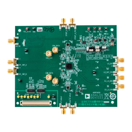
Page 3: Adrf6650 Evaluation Board Photograph
ADRF6650-EVALZ User Guide UG-1026 EVALUATION BOARD PHOTOGRAPH Figure 1. ADRF6650-EVALZ Evaluation Board Rev. A | Page 3 of 17... -
Page 4: Evaluation Board Hardware
450 MHz to 2700 MHz and the inputs must be ac-coupled. POWER SUPPLY The ADRF6650-EVALZ evaluation board requires a single, 5.6 V power source. The power supply design on the ADRF6650- EVALZ evaluation board consists of low dropout dc regulators that regulate the 5.6 V source to 3.3 V power rails for the main IC. -
Page 5: Lo Generation And External Lo Input
For the default configuration of the LO inputs on balun. For a single-ended output, use the IFOUT_B connector the ADRF6650-EVALZ, apply a single-ended LO input to the with the on-board balun. SMA labeled EX_LO_NEG, the on-board balun converts the signal to differential. -
Page 6: Evaluation Board Software And Quick Start Procedures
Find ACE.exe under the default path and double-click to run software. Alternatively, the software can run from the Start menu by navigating to the Analog Devices folder, and run the software under the ACE folder. ADRF6650 GRAPHICAL USER INTERFACE (GUI) -
Page 7: Adrf6650 Gui Components
ADRF6650-EVALZ User Guide UG-1026 Figure 6. ADRF6650 GUI Interface • The entry fields within the GUI enable manual entry of a ADRF6650 GUI COMPONENTS desired value (for example, see Figure 9). Input values are This section describes the components within the software written and entered by pressing Enter. -
Page 8: Checking The Usb Connectivity
When a controllable graphic displays as gray (see Figure 13), SDP-S board and the ADRF6650-EVALZ. the component is disabled. When a controllable graphic displays as blue (see Figure 14), the component is enabled. -
Page 9: Evaluation Board Schematics And Artwork
ADRF6650-EVALZ User Guide UG-1026 EVALUATION BOARD SCHEMATICS AND ARTWORK Figure 18. ADRF6650-EVALZ Schematic Rev. A | Page 9 of 17... - Page 10 UG-1026 ADRF6650-EVALZ User Guide CP_OUT VTUNE 4300PF 4300PF 0.12uF Figure 19. PLL Filter R131 IFOUT_B_POS R160 R133 2 NC 35.7 0.1uF C112 C107L26 TC1-1-13MX+ IFOUT_B R159 35.7 0.1uF Figure 20. IF Output Schematic R115 LO_OUT_POS R145 TCM1-83X+ LO_OUT R148 R101...
- Page 11 ADRF6650-EVALZ User Guide UG-1026 EX_LO_POS C101 R129 R146 EX_LO_IN+ TCM1-83X+ EX_LO_NEG 100PF C100 R130 R149 EX_LO_IN– 100PF R103 R102 R147 Figure 23. ADRF6650 PLL Schematic VCC_VCO C136 C141 120OHM C147 10UF R158 VCC_CP TP34 R107 SW_3V3_0 TP35 VCC_PFD R108 VCC_IN...
- Page 12 UG-1026 ADRF6650-EVALZ User Guide VCC_MIXER_A OPTIONAL SWITCHING TP20 TP25 SUPPLY CONNECTORS TP38 C119 120OHM VCC_MIXER_B C116 120OHM VCC_MIXER_LOA 120OHM VCC_MIXER_LOB C115 120OHM VCC_IF_AMP_A VCC_IN ADM7171ACPZ-3.3 R143 VOUT C118 120OHM VOUT C108 C109 C113 10uF 10uF VCC_IF_AMP_B SENSE C110 1000pF C120...
- Page 13 TP27 DGND SDP_RSTB C163 C159 DGND TP29 DGND C160 R128 TP30 DGND C161 DGND TP31 SDP_CSB DGND C162 DGND SDP_3V3 DGND DGND DGND Figure 26. SDP-S Connector Figure 27. ADRF6650-EVALZ Top Silk Screen Rev. A | Page 13 of 17...
- Page 14 UG-1026 ADRF6650-EVALZ User Guide Figure 28. ADRF6650-EVALZ Bottom Silk Screen Rev. A | Page 14 of 17...
-
Page 15: Ordering Information
ADRF6650-EVALZ User Guide UG-1026 ORDERING INFORMATION BILL OF MATERIALS Table 1. Qty. Reference Designator Description Manufacturer Part Number Murata GRM155R71C104KA88D C1, C4, C26, C32, C35, C51, C53, C56, Ceramic capacitors, X7R, general-purpose, C57, C61, C66, C72, C80, C90, C93, C94, 0.1 μF, C0402, 16 V... - Page 16 UG-1026 ADRF6650-EVALZ User Guide Qty. Reference Designator Description Manufacturer Part Number L3 to L6 Inductor surface mount, 270 nH, 0603CS Coilcraft 0603CS-R27XGLW P1 to P6, P10 PCB connectors, BERG header, solder Samtec TSW-103-08-G-S termination, male, 3-pin PCB connector, board to board receptacle,...
- Page 17 By using the evaluation board discussed herein (together with any tools, components documentation or support materials, the “Evaluation Board”), you are agreeing to be bound by the terms and conditions set forth below (“Agreement”) unless you have purchased the Evaluation Board, in which case the Analog Devices Standard Terms and Conditions of Sale shall govern. Do not use the Evaluation Board until you have read and agreed to the Agreement.
Need help?
Do you have a question about the ADRF6650-EVALZ and is the answer not in the manual?
Questions and answers