Table of Contents
Advertisement
Quick Links
One Technology Way • P.O. Box 9106 • Norwood, MA 02062-9106, U.S.A. • Tel: 781.329.4700 • Fax: 781.461.3113 • www.analog.com
FEATURES
Full-featured evaluation board for the
PC control in conjunction with the system demonstration
platform (EVAL-SDP-CB1Z)
PC software for control and data analysis (time and
frequency domain)
Standalone capability
ONLINE RESOURCES
Evaluation kit contents
AD7366/AD7367
evaluation board
Evaluation software CD for the
EVAL-AD7366/AD7367SDZ
9 V mains power supply adapter
Document needed for reference
AD7366/AD7367
data sheet
Required software
EVAL-AD7366SDZ/AD67SDZ evaluation software
Design and integration files
Schematics, layout files, and bill of materials
EQUIPMENT NEEDED
System demonstration platform (EVAL-SDP-CB1Z)
Precision analog signal source
SMB cables
USB cables
PC running Windows™ with USB 2.0 port
PLEASE SEE THE LAST PAGE FOR AN IMPORTANT
WARNING AND LEGAL TERMS AND CONDITIONS.
Evaluating the AD7366/AD7367
AD7366/AD7367
AD7366/AD7367
Rev. A | Page 1 of 20
Evaluation Board User Guide
GENERAL DESCRIPTION
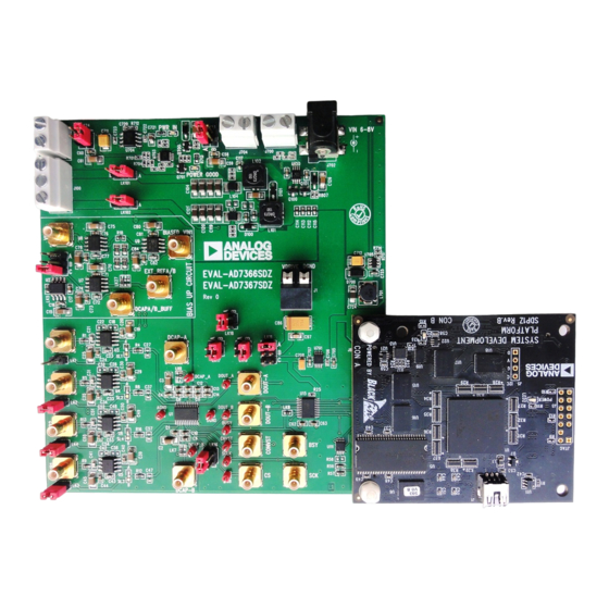
The EVAL-AD7366SDZ/EVAL-AD7367SDZ is a full-featured
evaluation board, designed to allow the user to easily evaluate
all features of the AD7366/AD7367. The evaluation board
can be control-led via the system demonstration platform
(SDP) connector (J8). The
EVAL-SDP-CB1Z
the evaluation board to be controlled via the USB port of a
PC using the
AD7366/AD7367
The EVAL-AD7366SDZ/EVAL-AD7367SDZ generates all
required power supplies on board and supplies power to the
EVAL-SDP-CB1Z
controller board.
On-board components include
•
AD8021: Low noise, high speed amplifier for 16-bit
systems
•
ADP1613: Step-up PWM dc-to-dc switching converter
•
ADP3303-5: High accuracy anyCAP™ 200 mA low dropout
linear regulator
•
ADP2301: 1.2 A 20 V, 1.4 MHz nonsynchronous step-
down switching regulator
•
ADP1720: 50 mA, high voltage, micropower linear
regulator
•
ADM1185: Quad voltage monitor and sequencer
•
ADG3308: Low voltage, 1.15 V to 5.5 V, 8-channel
bidirectional logic level translator
•
AD780: 5 V/3.0 V ultrahigh precision band gap voltage
reference
Various link options are described in the Evaluation Board
Hardware section.
UG-408
board allows
evaluation software.
Advertisement
Table of Contents

Related Manuals for Analog Devices AD7366


Summary of Contents for Analog Devices AD7366
-
Page 1: Features
PC control in conjunction with the system demonstration evaluation board, designed to allow the user to easily evaluate platform (EVAL-SDP-CB1Z) all features of the AD7366/AD7367. The evaluation board PC software for control and data analysis (time and can be control-led via the system demonstration platform frequency domain) (SDP) connector (J8). -
Page 2: Table Of Contents
Recommended Quick Start Steps ..........4 Description of User Software Panel ......... 14 Evaluation Board Hardware ............5 WaveForm Capture ..............15 AD7366/AD7367 Device Description ........5 AC Testing–Histogram .............. 16 Hardware Link Options ............... 6 DC Testing–Histogram ............. 16 Power Supplies ................ -
Page 3: Functional Block Diagram
SDP 5V ADP3303 ADP1720 3.3V OP AMP SUPPLIES BF527 VDRIVE VDRIVE CNVST ADG3308 SCLK LEVEL SHIFTER SERIAL AD8021 INTERFACE BUSY AD7366/AD7367 DOUTA DOUTB AD8021 RANGE0 RANGE1 EVAL-SDP-CB1Z REFSEL HARDWARE CONTROLLER ADDR AGND DGND SELECT BOARD AD8021 BIAS UP AD8021 CIRCUIT... -
Page 4: Quick Start Guide
AD7366SDZ/EVAL-AD7367SDZ board as shown in Figure 2. Launch the EVAL-AD7366SDZ/EVAL-AD7367SDZ Screw the two boards together with the enclosed nylon software from the Analog Devices subfolder in the screw-nut set to ensure the boards connect firmly together. Programs menu. Figure 2. Hardware Configuration—Setting Up the Evaluation Board... -
Page 5: Evaluation Board Hardware
±12 V V and V supplies are required for the ±12 V AD7366/AD7367 are fabricated on the Analog Devices, input range. Inc., industrial CMOS process (iCMOS2), which is a tech- nology platform combining the advantages of low and high... -
Page 6: Hardware Link Options
Ensure LK6 or LK7 is in the appropriate position. LK11 VDRIVE Voltage Selection. Sets the voltage at the VDRIVE pin of the AD7366/AD7367. Position A: VDRIVE connected to on-board 5 V. Position B: Externally supplied voltage supplied via J1. - Page 7 Evaluation Board User Guide UG-408 Link No. Function LK23 DVCC Source Selection. Position A: DVCC to AD7366/AD7367 supplied from on-board 5 V supply. Position B: DVCC to AD7366/AD7367 supplied from external supply via J704. LK24 AVCC Source Selection. Position A: AVCC to AD7366/AD7367 supplied from on-board 5 V supply.
-
Page 8: Power Supplies
16-bit systems. The outputs from may be connected to J700 to supply 7 V to 9 V. these amplifiers are connected to the AD7366/AD7367 via a Each supply is decoupled on the EVAL-AD7366SDZ/EVAL- low-pass RC filter network. -
Page 9: Basic Hardware Setup
UG-408 the power supplies on the evaluation board. The EVAL- BASIC HARDWARE SETUP AD7366SDZ/EVAL-AD7367SDZ requires an external power AD7366/AD7367 evaluation board connects to the supply, which is included in the evaluation board kit. Connect (EVAL-SDP-CB1Z) system demonstration board. The this power supply to the connector J702 on the EVAL-... -
Page 10: Replaced Evaluation Board Software Section
CD. Click the setup.exe file from the CD to run the install. The default location for the software is C:\Program Files\Analog Devices\AD7366/AD7367. It is important to install the evaluation software before connecting the evaluation board and the EVAL-SDP-CB1Z board to the USB port of the PC. - Page 11 Evaluation Board User Guide UG-408 Figure 11. ADI EVAL-SDP-CB1Z Drivers Setup Window 4 Figure 8. ADI EVAL-SDP-CB1Z Drivers Setup Window 1 Figure 12. ADI EVAL-SDP-CB1Z Drivers Setup Window 5 Figure 9. ADI EVAL-SDP-CB1Z Drivers Setup Window 2 Figure 10. ADI EVAL-SDP-CB1Z Drivers Setup Window 3 Rev.
-
Page 12: Launching The Software
AD7366/AD7367 evaluation board to the EVAL-SDP-CB1Z From the Start menu, select Programs>Analog as described in the Evaluation Board Hardware section. Devices>AD7366/AD7367. The main window of the software then displays. When you first plug in the EVAL-SDP-CB1Z board via the USB... -
Page 13: Removed Evaluation Board Schematics And Artwork Section 12 Added Figure 15 To Figure 19; Renumbered Sequentially
Evaluation Board User Guide UG-408 Figure 15. User Software Panel Rev. A | Page 13 of 20... -
Page 14: Description Of User Software Panel
Figure 15) from the ADC. Click again to stop sampling. Drop-down menu (labeled 2 in Figure 15) is used to select the generic AD7366 or AD7367. The resolution of selected part is This LED (labeled 10 in Figure 15) indicates when a read is in displayed. -
Page 15: Waveform Capture
Evaluation Board User Guide UG-408 Figure 16. Waveform Capture Tab WAVEFORM CAPTURE Figure 16 illustrates the waveform capture tab. The input signal The waveform analysis (labeled 1) reports back the amplitudes here is a 50 kHz sine wave. recorded from the captured signal in addition to the frequency of the signal tone. -
Page 16: Ac Testing-Histogram
UG-408 Evaluation Board User Guide Figure 17. Histogram Capture Tab AC TESTING–HISTOGRAM Figure 17 shows the histogram capture tab. This tests the ADC The area labeled as 1 in Figure 17 Illustrates the different for the code distribution for ac input. In addition, it computes measured values for the data captured. -
Page 17: Ac Testing-Fft Capture
Evaluation Board User Guide UG-408 Figure 18. FFT Capture Tab AC TESTING–FFT CAPTURE Figure 18 shows the FFT capture tab. This tests the traditional band-pass filter when the full-scale input range is more than a few V p-p, it is recommended to use the on-board amplifiers to ac characteristics of the converter and displays a fast Fourier transform (FFT) of the results. -
Page 18: Summary Tab
UG-408 Evaluation Board User Guide Figure 19. Summary Tab SUMMARY TAB Figure 19 shows the summary tab. This tab captures display information and provides this data in one panel with a synopsis of the information, including key performance parameters, such as SNR and THD. -
Page 19: Save File
(see Figure 21). The default Figure 20). location for the example files is C:\Program Files\Analog Devices\AD7366\examples. Users are prompted with a Save dialog box and should save to an appropriate folder location Figure 20. Save File Dialog Box Figure 21. - Page 20 By using the evaluation board discussed herein (together with any tools, components documentation or support materials, the “Evaluation Board”), you are agreeing to be bound by the terms and conditions set forth below (“Agreement”) unless you have purchased the Evaluation Board, in which case the Analog Devices Standard Terms and Conditions of Sale shall govern. Do not use the Evaluation Board until you have read and agreed to the Agreement.
Need help?
Do you have a question about the AD7366 and is the answer not in the manual?
Questions and answers