Table of Contents
Advertisement
Quick Links
Advertisement
Table of Contents

Related Manuals for Presys TA-60NL


Summary of Contents for Presys TA-60NL
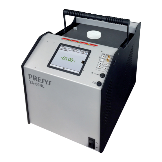
- Page 1 Temperature Advanced Calibrators TA-60NL Technical Manual EM0374-00...
- Page 3 The warranty conditions are available in our sites: www.presys.com.br/warranty...
-
Page 4: Table Of Contents
PRESYS Instruments TA-60NL Table of Contents 1.0 - Introduction ......................1 1.1 - Technical Specifications ..................2 1.1.1 - Input Technical Specifications ................ 3 1.1.2 - Special Software Features................4 1.2 - Order Code ......................4 1.3 - Accessories ......................5 1.4 - Parts Identification .................... -
Page 5: Introduction
RTD, TC and mA, stirred liquid and blackbody source. TA-60NL calibrator model generates temperatures from -60 ºC to 140 ºC The calibrator also provides an input for an external probe to perform the... -
Page 6: Technical Specifications
PRESYS Instruments TA-60NL Another way of performing automatic documented calibrations is by means of Calibration Software for PC/Windows , which uses USB communication or Ethernet to connect the computer. TA Calibrators have also many other features, such as: RTD input for 2, 3 and 4 wires. Table IEC 60751, JIS or Callendar-Van Dusen user-configurable. -
Page 7: Input Technical Specifications
PRESYS Instruments TA-60NL 1.1.1 - Input Technical Specifications Input Ranges Resolution Accuracy Remarks 0.005 % FS* 0 to 400 Ω 0.01 Ω Ext. Probe¹ 0.01 C / 0.01 F 0.05 C / 0.1 F IEC 60751 Ext. Probe¹ -200 to 850 °C /-328 to 1562 °F ... -
Page 8: Special Software Features
PRESYS Instruments TA-60NL 1.1.2 - Special Software Features Special Functions: SCALE: makes the scaling of mA input. STEP: steps or set points with configurable time. Memory Manager: stores configuration types predefined by the user. Automated Tasks: creating of calibration work orders and automatic execution of calibration services, storage of data and reporting. -
Page 9: Accessories
PRESYS Instruments TA-60NL 1.3 - Accessories Dry Block Insert: Inserts Holes Order Code IN01 1 x 3/4" 06.04.0041-00 IN02 1 x 1/2" 06.04.0042-00 IN03 1 x 6.0mm and 3 x 1/4" 06.04.0043-00 IN04 3 x 6.0mm and 1 x 1/4"... - Page 10 PRESYS Instruments TA-60NL Description Order Code Insert Extractor 02.06.0085-20 Lead Cable Kit 06.07.0018-00 Power Cable Type J – Brazil 01.14.0008-21 Power Cable Type B – US 01.14.0100-21 Power Cable Type F – Europe Universal 01.14.0089-21 Power Cable Type J – UK 01.14.0117-21...
-
Page 11: Parts Identification
PRESYS Instruments TA-60NL 1.4 - Parts Identification Fig. 01 - Parts Identification Page 7... -
Page 12: Instructions For Optional
PRESYS Instruments TA-60NL 1.5 - Instructions for Optional Stirred Liquid Kit Fig. 02 - Uses of Stirred Liquid Kit Page 8... - Page 13 How less viscous, how better the fluid circulation will be and homogeneous heat produced in the middle. We recommend using the following heat transfer fluids for model TA-60NL: Viscosity Fluid...
- Page 14 PRESYS Instruments TA-60NL Black Body Insert (BB) Placing the insert BB inside the well of the block of the calibrator provides it with a good black-body cavity with emissivity above 0.95, suitable for calibration of infrared thermometer. For more accurate measurements use a calibrated probe placed in the side hole of the bath and connected to the external probe input.
-
Page 15: Calibrator Operation
PRESYS Instruments TA-60NL 2.0 - Calibrator Operation When powered on, the calibrator goes through a self-test routine and shows the last adjustment date and it is ready to operate. After the self-test is completed, the display shows the main menu: Fig. -
Page 16: Calibrator Menu
PRESYS Instruments TA-60NL 2.1 - Calibrator Menu To select the probe set point or electrical input functions, from the main menu, press the CALIBRATOR button. The following screen is displayed. Fig. 05 - Calibrator Function At the top is shown the probe settings and values. - Page 17 PRESYS Instruments TA-60NL In the STEP function, a step value can be configured, and the steps can be changed through the up and down arrows. In REFERENCE menu, you can configure the type of probe reference (see section 2.1.1 – Probe Reference). The chosen reference appears just below the REFERENCE button.
-
Page 18: Probe Settings
PRESYS Instruments TA-60NL 2.1.1 - Probe Settings There are two different references to control the thermal block: Internal Reference and External Reference. The Internal Reference is a sensor built into the block. The External Reference is an option for more accurate measurements. The control reference comes from a Standard Sensor placed inside the insert, among the DUT (devices under test). - Page 19 PRESYS Instruments TA-60NL Fig. 09 - Adding a new Reference Sensor After filling the blanks, click on SAVE button and confirm. The new sensor is now available to be chosen in the list. To edit data from a sensor, select it and press MANAGER button.
-
Page 20: Input Settings
PRESYS Instruments TA-60NL 2.1.2 - Input Settings The INPUT menu has the following options: Fig. 11 - Input Menu Options For OHM measurement, you should also select between 2, 3 or 4 wires options. For RTD input, it should be chosen the type between Pt-100, Pt-1000, Cu-10 or Ni-100 (standard table used), the number of lead wires (2, 3 or 4 wires) and the temperature scale (ITS-90 or IPTS-68). - Page 21 PRESYS Instruments TA-60NL compensation is done internally; In Manual you must provide the value of the temperature of the cold junction to the calibrator. The option SWITCH has two ways to be used. When entering the SWITCH function, the input works as a continuity measurement between RTD2 and RTD4 terminals.
- Page 22 PRESYS Instruments TA-60NL 2.1.2.1 - Input Connections Diagrams Fig. 15 - Input Connections Page 18...
-
Page 23: Special Function
PRESYS Instruments TA-60NL 2.1.3 - Special Function SCALE: For the current input, it is possible to use the scale function: Fig. 16 - Option for mA Input: SCALE It establishes a linear relationship between the mA input signal and what is shown at the display, according to the graphic below: Fig. -
Page 24: Saving Current Configuration (Memory Manager)
PRESYS Instruments TA-60NL Fig. 18 - Scale Function Configuration Note: To enable the Scale Function, turn the function ON before touching OK button. To disable, turn the function OFF. 2.1.4 - Saving Current Configuration (Memory Manager) The TA Series calibrators admit several special functions that may become of frequent use. -
Page 25: Hart Configuration
PRESYS Instruments TA-60NL ® 2.2 - HART Configuration The TA Series Calibrators can be used to read and set parameters in devices that ® ® have HART Communication Protocol. HART Protocol allows digital communication between master (in this case, the TA Calibrator) and the slave (field instrument) superimposed on the 4-20 mA analog signal. -
Page 26: Starting Communication
PRESYS Instruments TA-60NL Fig. 20 - Transmitter Powered by an External Power Supply ® mA INPUT + HART (Internal Resistor Enabled) 2.2.2 - Starting Communication ® ® After defining HART connection type, inform the ADDRESS of the HART device and press the CONNECT button. -
Page 27: Transmitter With Reference
PRESYS Instruments TA-60NL ® Fig. 21 - Adjusting the measuring range of the HART transmitter ® 2.2.4 - Adjusting the Measurement Range of a HART Transmitter with Reference Another way to adjust the range of the transmitter is generating the minimum and maximum values of the desired range in the transmitter input and adjusting these values as minimum and maximum (set by reference). -
Page 28: Adjusting The Measurement Range Of A Hart
PRESYS Instruments TA-60NL MONITOR tab. In this screen are shown the value of the primary variable (PV) read by ® HART (digital), the current that the transmitter wants to generate (AO - DIGITAL OUTPUT), and the current measured by the TA Calibrator (ANALOGIC READ). Set the block temperature pressing OUTPUT and adjust the transmitter range pressing the ↓... -
Page 29: Automatic Tasks
PRESYS Instruments TA-60NL ® Fig. 24 - Checking / Adjusting the mA HART Transmitter Output 2.3 - Automatic Tasks In TA Calibrators, automatic calibration tasks can be created and performed. This option can be used to generate calibration work orders for sensors, transmitters and indicators. - Page 30 PRESYS Instruments TA-60NL Go to the As Found/ As Left tab. Add each point to be generated by the TA Calibrator and the expected value for the UUT (unit under test) both As found (calibration done before adjustment) and As left (calibration done after adjustment) values.
-
Page 31: Performing Tasks
PRESYS Instruments TA-60NL Go to the Review and Save tab and choose an identification name/number for your task. If you want to save the model of this task for later use to create other tasks, press SAVE TEMPLATE and give a name for it. When you want to open this model again, open the task creation screen and press OPEN TEMPLATE in Task info tab. -
Page 32: Viewing Results
PRESYS Instruments TA-60NL The TA Calibrator automatically starts the execution of the calibration, generating the registered setpoints, waiting the stabilization of the system and reading the associated input values. If you selected the option NONE as input, for each generated point, the calibrator will require to digit the value of the temperature indicated by the instrument (thermometer, indicator…). -
Page 33: Data-Logger
PRESYS Instruments TA-60NL To print the Calibration Report, press the printer icon . The printer must have been previously configured in SETTINGS > SYSTEM > PRINTER CONFIG. The Report logo can be changed for one of your own company. For this, connect a USB cable between TA Calibrator USB Device port and a computer. - Page 34 PRESYS Instruments TA-60NL Fig. 32 - Data Logger In configuration menu (icon , you can edit the background color of the chart, color and line thickness, sampling rate (in seconds) and set the x (time) and y (measurements) axis of the chart.
-
Page 35: Videos
PRESYS Instruments TA-60NL 2.5 - Videos TA Series calibrators have a video player. These videos can be viewed while a calibration is performed and are used to help operator to learn about some specific internal procedures. From the main menu, selecting VIDEOS a list of video categories appears. Select the category and the desired video. -
Page 36: Network
PRESYS Instruments TA-60NL The instrument initially has no access password. This setting can be changed in SECURITY OPTIONS. To create a new user, press the key icon and then users icon . Fill the blanks and press CREATE. It is possible to add a signature that will be used on the calibration report. - Page 37 PRESYS Instruments TA-60NL To verify the IP address press the button indicated below. Fig. 34 - IP address Fig. 35 - TA Calibrator Web Server In the Web Server, you can monitor the calibrator screen, change the setpoint and see the auxiliary input readings.
-
Page 38: Safety Instructions
4 - Recommendations as regards Accuracy of Measurements PRESYS Temperature Advanced Calibrators are instruments of high accuracy level, requiring the observation of all the procedures described in this section, in order to achieve the necessary conditions to get the accuracy levels during the calibrations. -
Page 39: Calibration (Adjustment)
PRESYS Instruments TA-60NL 5 - Calibration (Adjustment) Warning: Enter the following options only after understanding them completely. Otherwise, it may be necessary to return the instrument to the factory for recalibration! Select ADJUST/CAL option from the SETTINGS > SYSTEM menu. You should then enter the password 9875 to access the calibration menu. - Page 40 PRESYS Instruments TA-60NL resistors Point 1 Point 2 20.000 50.000 OHM3 100.000 500.000 OHM2 500.000 2200.000 OHM1 The cold junction calibration (Thermocouple) is performed measuring the mV(-) terminal temperature. Store only the point 1.
-
Page 41: Probe Calibration
The option to adjust the internal sensor has seven points of adjustment. These points are recorded via points 1 to 7. Before starting the calibration (adjustment), record in these points the respective initial storing values, according to the table below: For the TA-60NL Calibration Initial value Standard... -
Page 42: Maintenance
Replace the fuse once. If a second fuse blows again, it is because the fault is not that simple. In this case, contact the Presys technical support. In case of malfunction of mA input, the input fuse (250 V/32 mA) can be exchanged.
Need help?
Do you have a question about the TA-60NL and is the answer not in the manual?
Questions and answers