
Related Manuals for Presys DCY-2058


Summary of Contents for Presys DCY-2058
- Page 1 PRESYS Instruments Auto-Manual / Auto / Manual Stations DCY-2058 / 2059 PRESYS DCY-2058 AUTO / MANUAL PRESYS DCY-2059 AUTO/MANUAL TECHNICAL MANUAL...
-
Page 2: Table Of Contents
PRESYS ⏐ Instruments DCY-2058 and DCY-2059 Table of Contents 1.0 - Introduction ......................1 1.1 - Description......................1 1.2 - Order Code Number ....................2 1.3 - Technical Specifications ..................3 2.0 - Installation ........................4 2.1 - Mechanical Installation ...................4 2.2 - Electrical Installation....................4 2.3 - Process Input Signal Connection ................5... -
Page 3: Introduction
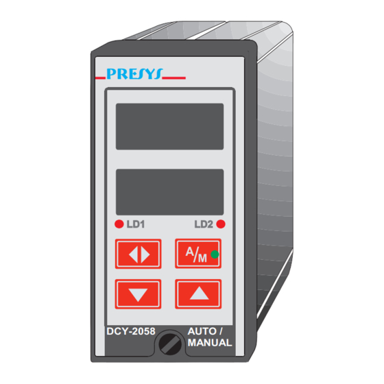
They accept 90 to 240VAC or 130 to 340VDC (with any polarity) power supply. Other ranges are also available. Fig. 1 - DCY-2058/2059 Stations Front Panels. The instruments are housed in an extruded aluminum case which makes them highly immune to electrical noise, electromagnetic interference and resistant to the most severe and rough industrial use conditions. -
Page 4: Order Code Number
1 or 2. 1.2 - Order Code Number Note 1: DCY-2058/2059 Stations configuration is described in detail by this technical manual and can be easily done by the user. If desired, specify the configuration so that the instrument is configured at Presys. -
Page 5: Technical Specifications
PRESYS ⏐ Instruments DCY-2058 and DCY-2059 1.3 - Technical Specifications Inputs: • Two inputs configurable for 4 - 20mA (R = 250Ω), 1 - 5VDC (R > 10MΩ) and 0 - 10VDC (R > 2MΩ). Table 1 shows the resolution for the linear input sensors. -
Page 6: Installation
2.0 - Installation 2.1 - Mechanical Installation The DCY-2058 and 2059 Stations front panels have 1/8DIN size (48 x 96mm). They are fixed by the rails which press them against the back side of the panel. After preparing a 45 x 92mm cut in the panel, remove the rails from the Station and slide its rear through the cut until its front reaches the panel. -
Page 7: Process Input Signal Connection
Signal wiring must be kept far away from power wires. Due to its metal case the instrument ground should be connected to earth ground. Never connect the ground to neutral terminal. Fig. 3 - DCY-2058 and 2059 Station Terminals 2.3 - Process Input Signal Connection DCY-2058... -
Page 8: Milliampere Input
PRESYS ⏐ Instruments DCY-2058 and DCY-2059 2.3.1 - Milliampere Input A standard 4 to 20mA current source can be applied between terminals 1(+) and 3(-) in case of input 1, and between terminals 4(+) and 6(-) in case of input 2; such current can originate from an externally powered Transmitter. -
Page 9: Voltage Input
PRESYS ⏐ Instruments DCY-2058 and DCY-2059 2.3.2 - Voltage Input 0 to 5VDC voltage must be applied between terminals 2(+) and 3(-) in case of input 1 and between terminals 5(+) and 6(-) in case of input 2. 0 to 10VDC voltage must be applied between terminals 1(+) and 3(-) in case of input 1 and between terminals 4(+) and 6(-) in case of input 2. -
Page 10: Output Signal Connection
PRESYS ⏐ Instruments DCY-2058 and DCY-2059 2.4 - Output Signal Connection In their most complete versions (dual loop) the Stations can be provided with up to two output signals: output 1 and output 2. Output 1 is used both in the dual loop and single loop Stations. -
Page 11: Connection Diagram
PRESYS ⏐ Instruments DCY-2058 and DCY-2059 2.5 - Connection Diagram Installation Page 9... -
Page 12: Communication
PRESYS ⏐ Instruments DCY-2058 and DCY-2059 2.6 - Communication The DCY-2058 and 2059 Stations can communicate with computers via RS-232 or RS-422/485 since the communication optional module is installed and the communication parameters are configured. 2.7 - Engineering Units A label containing a selection of Engineering Units is supplied with each Station. -
Page 13: Operation
3.0 - Operation 3.1 - Normal Operation The DCY-2058 and 2059 Auto-Manual / Auto / Manual Stations are provided with two operational modes: normal operation mode and configuration mode. In normal operation mode we can further have the automatic operation mode and the manual operation mode, depending on the configuration of the Station. - Page 14 PRESYS ⏐ Instruments DCY-2058 and DCY-2059 Operation Level Fig. 7 - Operation Level Options At the operation level, the keys on the Auto-Manual Station front panel have the following functions: Tecla Função Switches from automatic mode to manual mode and vice-versa.
-
Page 15: Configuration
CONF option. 3.2 - Configuration The DCY-2058 and 2059 Stations can be configured with a password system to prevent unauthorized people from altering critical process parameters. Therefore, whenever the UP key is pressed while the CONF mnemonic... - Page 16 NVRAM) and determine the instrument normal operation. Through configuration parameters the user may adapt the instrument according to his requirements. Normally the DCY-2058 and 2059 Stations are factory configured and the user is not expected to enter the configuration mode. However, nothing prevents the user from reconfiguring the instrument in case a new application so requires.
- Page 17 ⏐ Instruments DCY-2058 and DCY-2059 great variety of operation modes and the universal characteristics of the two inputs in the DCY-2058 and 2059 Stations. The configuration parameters are distributed over 5 increasing hierarchical levels as shown in figure 9. In order to go through those levels and to have access to their corresponding...
- Page 18 PRESYS ⏐ Instruments DCY-2058 and DCY-2059 The hierarchical levels are shown below. A step by step explanation is given for the options in each level, with all the corresponding parameters. Within each level, the instrument front panel keys have the following functions: Tecla Função...
-
Page 19: Level 1 - General
PRESYS ⏐ Instruments DCY-2058 and DCY-2059 3.2.1 - Level 1 - General In level 1 we have the options: TAG, SOFT, PASS, TYPE and ST.CO (see figure 10). Fig. 10 - GENERAL Level Options Operation Page 17... - Page 20 PRESYS ⏐ Instruments DCY-2058 and DCY-2059 TAG - this option is a numeric identification for the instrument. The procedure to enter the tag or any other parameter is the same as for the previously described password (see the functions of the ENTER, UP and DOWN keys on Configuration section).
- Page 21 PRESYS ⏐ Instruments DCY-2058 and DCY-2059 The adjustable parameter ranges shown on figure 10 are given below: Factory Mnemonic Parameter Adjustable Span Unit Value instrument 2058 -999 to 9999 ----------- identification 2059 SOFT software version ------------- 1.31 ----------- VALUE user password...
-
Page 22: Level 2 - Input
PRESYS ⏐ Instruments DCY-2058 and DCY-2059 3.2.2 - Level 2 - Input The Input Level allows to select the sensor type for each channel. The sensor types available are the linear inputs (0 to 5V, 0 to 10V, 0 to 20 mA) as illustrated in figure 11. - Page 23 PRESYS ⏐ Instruments DCY-2058 and DCY-2059 The range of the adjustable parameters shown on figure 11 is given below. Factory Mnemonic Parameter Adjustable Unit Value percentage of the input full scale (20mA, 5V or LIM LOW 0.0 to 100.0 10V), associated to...
-
Page 24: Level 3 - Output
PRESYS ⏐ Instruments DCY-2058 and DCY-2059 DEC.PT - sets the decimal point to exhibit the engineering units on the upper display. It can be configured up to three decimal digits. OFSET - it allows the user to enter a fixed offset value (in engineering units) to be added to the value shown on the upper display. - Page 25 PRESYS ⏐ Instruments DCY-2058 and DCY-2059 The adjustable parameter span shown on figure 13 is given below. Factory Mnemonic Parameter Adjustable Span Unit Value PT. 0, 0.0, PT. 1, 100.0, PT. 2, Percentage output 0.0, indication span used for output signal linearization.
- Page 26 PRESYS ⏐ Instruments DCY-2058 and DCY-2059 The output signal can be linearized configuring the LINEAR option. See the graphic bellow: Fig. 15 - Linearization of the Output Signal The parameters LIN. 0 to LIN. 10 corresponds to the percentage of the output signal full scale.
-
Page 27: Level 4 - Calibration
PRESYS ⏐ Instruments DCY-2058 and DCY-2059 The output inverse indication is common when dealing with a normally opened valve, i.e., 4mA maintains the valve opened. Thus, the 100% indication on the display refers to the maximum flow through the valve which corresponds to the instrument 4 mA output. -
Page 28: Maintenance
PRESYS ⏐ Instruments DCY-2058 and DCY-2059 4.0 - Maintenance 4.1 - Station Hardware The Station maintenance requires the user to have access to the instrument hardware. The Station hardware is divided into three main circuit boards: the Display Board, the CPU Board and the Power Supply Board. The three circuit boards are attached to the aluminum case by only one screw located at the front panel. -
Page 29: Hardware Configuration
PRESYS ⏐ Instruments DCY-2058 and DCY-2059 4.2 - Hardware Configuration The input level software configuration (level 2 - INPUT) must be complemented by the input configuration by hardware using internal jumpers. There are four places for the installation of jumpers for channel 1: J5, J6, J7 and J8;... -
Page 30: Optional Module Connection
Fig. 18 - Jumpers on dummy positions for 0 to 10V input 4.3 - Optional Module Connection The DCY-2058 and 2059 Stations may be provided with up to two output plus communication. For that purpose, the corresponding optional modules should be installed inside the instrument. - Page 31 MOD 3 and MOD 4. MOD 1 and MOD 2 are connected, respectively, to the modules corresponding to output 1 and output 2. MOD 3 and MOD 4 have no use in DCY-2058 / 2059 and must be kept unconnected. The plug-in connection for the communication module is located on the CPU Board and has no denomination.
-
Page 32: Calibration
Otherwise it might be necessary to send the instrument back to factory for recalibration. Calibration in this manual means adjustment. The DCY-2058 and 2059 Stations are accurately calibrated at factory and will not require periodic recalibration under normal conditions. If, for any reason, a recalibration is required, follow the procedure described below. - Page 33 PRESYS ⏐ Instruments DCY-2058 and DCY-2059 In order to return to normal operation move back through the hierarchical levels until reaching level zero. Figure 22 shows the input and output calibration options for calibration level 4. Fig. 22 – CALIBRATION Level Options...
- Page 34 PRESYS ⏐ Instruments DCY-2058 and DCY-2059 Calibration of voltage input (0 to 5V) In order to calibrate the voltage input (0 to 5V) connect an accurate DC voltage source to the channel to be calibrated (terminals 2(+) and 3(-) for channel 1 or 5(+) and 6(-) for channel 2).
- Page 35 PRESYS ⏐ Instruments DCY-2058 and DCY-2059 Output calibration Analog outputs can be calibrated by the Stations themselves. Output 1 can be calibrated by input 1 and output 2 can be calibrated by input 2. The configuration of input hardware should be the same as for the output (0 to 5V, 0 to 10V or 0 to 20mA) since the Stations themselves will be measuring the output signal.
-
Page 36: Hardware Maintenance Instructions
PRESYS ⏐ Instruments DCY-2058 and DCY-2059 Returning to factory calibration The Stations store the factory calibration parameters in the non-volatile memory whick can be retrieved at any time. Should there be any suspicion that some instrument malfunction might be due to an improper recalibration procedure use the REC option (see figure 22). - Page 37 PRESYS ⏐ Instruments DCY-2058 and DCY-2059 Check if the voltages on flat cable 1 as shown in figure 23 are close to values in table 8 and if they are present on the CPU Board. Points of Flat-cable 1 Voltages...
-
Page 38: List Of Components
PRESYS ⏐ Instruments DCY-2058 and DCY-2059 4.6 - List of Components Display Circuit Board Code Components Reference 01.05.0051-20 Display Board - DCY 2058 --------------------- 01.05.0054-20 Display Board - DCY 2059 --------------------- 01.07.0003-21 Display 9 mm --------------------- 01.07.0002-21 Display 14 mm --------------------- 01.04.0001-21... - Page 39 PRESYS ⏐ Instruments DCY-2058 and DCY-2059 Code Components Reference 01.02.0082-21 Resistor 10K R5,20,21 01.02.0116-21 Resistor 18K 01.02.0083-21 Resistor 20K 01.02.0110-21 Resistor 27K 01.02.0085-21 Resistor 47K 01.02.0106-21 Resistor 150K 01.02.0088-21 Resistor 470K 01.02.0006-21 Resistor 20R 01.02.0183-21 Resistor 2K32 01.02.0108-21 Resistor 15K4 01.06.0003-21...
- Page 40 PRESYS ⏐ Instruments DCY-2058 and DCY-2059 Code Components Reference 01.02.0030-21 Resistor 4K42 R8,9 01.02.0031-21 Resistor 4K99 01.02.0036-21 Resistor 8K66 01.02.0038-21 Resistor 10K R20,39 01.02.0046-21 Resistor 40K2 01.02.0075-21 Resistor 1K R19,22,30 01.02.0078-21 Resistor 2K 01.03.0038-21 Radial electrolytic capacitor 10 uF X 16 V C17,28,23,26,31 01.02.0082-21...
-
Page 41: List Of Recommended Spare Components
PRESYS ⏐ Instruments DCY-2058 and DCY-2059 Code Components Reference 01.02.0038-21 Resistor 10K 1% 01.02.0047-21 Resistor 49K9 1% R7,8 01.02.0059-21 Resistor 301K 1% 01.02.0069-21 Resistor 1M 1% 01.02.0109-21 Resistor 3K3 5% 01.02.0080-21 Resistor 4K7 5% 01.17.0001-21 Pin bus 2 x 2 J1,2 01.17.0004-21... - Page 42 PRESYS INSTRUMENTOS E SISTEMAS LTDA. RUA LUIZ DA COSTA RAMOS, 260 - SAUDE SAO PAULO SP BRAZIL 9001 04157-020 - PHONE +55 (11) 5073.1900 - FAX +55 (11) 5073.3366...
Need help?
Do you have a question about the DCY-2058 and is the answer not in the manual?
Questions and answers