
Subscribe to Our Youtube Channel
Related Manuals for Presys DMY-2011


Summary of Contents for Presys DMY-2011
- Page 1 PRESYS Instruments DMY-2011 / 2035 / 2036 Universal Process Indicators PRESYS PRESYS A C K A C K A C K DMY-2035 DMY-2011 PRESYS DMY-2036 A C K TECHNICAL MANUAL...
-
Page 2: Table Of Contents
PRESYS Instruments DMY-2011, DMY-2035 and DMY-2036 TABLE OF CONTENTS Page 1 - Introduction..................1.1 - Description..................1.2 - Order Code..................1.3 - Technical Specifications..............2 - Installation................... 2.1 - Mechanical Installation..............2.2 - Electrical Installation................ 2.3 - Process Input Signal Connection............. -
Page 3: Introduction
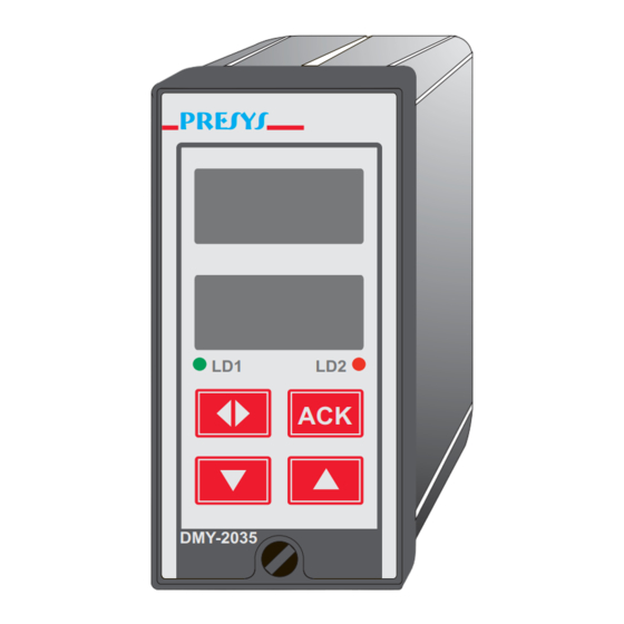
DMY-2011, DMY-2035 and DMY-2036 1 - Introduction 1.1 - Description PRESYS DMY-2011, 2035 and 2036 Indicators are microprocessor-based instruments that show all kind of industrial process variable, such as: temperature, pressure, flow and level. They have non-volatile internal memory (E2PROM) to store calibration values. - Page 4 PRESYS Instruments DMY-2011, DMY-2035 and DMY-2036 (1) PLACE FOR STICKING THE PRESYS ENGINEERING UNITS (2) CHANNEL 1 PROCESS VARIABLE DISPLAY (3) CHANNEL 2 PROCESS VARIABLE DISPLAY (4) CONFIGURABLE SIGNALING LEDS ENTER ACKNOWLEDGE DOWN KEY UP KEY DMY-2035 SCREW FOR INDICATOR...
-
Page 5: Order Code
PRESYS Instruments DMY-2011, DMY-2035 and DMY-2036 1.2 - Order code Order Code DMY - 2011 / 2035 / 2036 - Field A Output 1 Not used 4 to 20mA 1 to 5V 0 to 10V SPST relay Open collector voltage... - Page 6 1) DMY - 2011 - 0 - 0 - 1 - 1 - 1 - 0 - 0 This code defines a DMY-2011 Indicator with two SPDT relays which can be used as high and low alarms, 90 to 240VAC or 130 to 340VDC electric power supply, protected field usage.
-
Page 7: Technical Specifications
PRESYS Instruments DMY-2011, DMY-2035 and DMY-2036 1.3 - Specifications Inputs: • Two inputs configurable for thermocouple (J, K, T, E, R, S, under ITS-90), Pt-100 RTD under DIN 43760, 4 to 20mA, 0 to 55mVDC, 1 to 5VDC and 0 to 10VDC. Input impedance of 250Ω for mA, 10MΩ for 5VDC and 2MΩ above 5VDC. - Page 8 Panel cut of 92 × 92 mm. 1/8 DIN (48 × 96 mm) with 162 mm depth. 2035/2036 Panel cut of 45 × 92 mm. Weight: 0.5 kg approx (DMY-2035/36) / 0.6 kg nominal (DMY-2011). Warranty: One-year warranty. Introduction Page 6...
-
Page 9: Installation
PRESYS Instruments DMY-2011, DMY-2035 and DMY-2036 2 - Installation 2.1 - Mechanical Installation The front panel of the DMY - 2035 / 2036 Indicators has 1/8 DIN size (48 × 96 mm) and the front panel of the DMY - 2011 Indicator has 1/4 DIN size (96 ×... -
Page 10: Electrical Installation
PRESYS Instruments DMY-2011, DMY-2035 and DMY-2036 Warning: follow indicated directions when mounting rails.. Attachment screw Figure 4 - Dimensional drawing, panel mounting cutout and side view for DMY-2011 Indicator 2.2 - Electrical Installation DMY - 2011, 2035 and 2036 Indicators may be powered by voltage between 90 and 240VAC or 130 to 340VDC, any polarity. -
Page 11: Process Input Signal Connection
PRESYS Instruments DMY-2011, DMY-2035 and DMY-2036 Figure 5 - Indicator Terminals 2.3 - Process Input Signal Connections. The Indicators accept the connection of thermocouple, 2 or 3-wire RTD, mA, mV or V. See the different types and ranges of input sensors in table 1, section 1.3 on Technical Specifications. -
Page 12: Thermocouple Input
PRESYS Instruments DMY-2011, DMY-2035 and DMY-2036 The connection of a certain type of sensor in input 1 does not restrict the use of other sensor in input 2. In order to avoid noise in the wiring, use twisted pair cable and cross sensor connection wire inside a metallic tube or use shielded cable. -
Page 13: Rtd Input
PRESYS Instruments DMY-2011, DMY-2035 and DMY-2036 2.3.2 - RTD Input An RTD input device may be a 2-wire, 3-wire or 4-wire RTD. All types of connection are shown in figure 7. A 2-wire RTD is connected to terminals 1 and 3 when using input 1 and to terminals 4 and 6 when using input 2 as shown in figure 7. -
Page 14: Milliampere Input
PRESYS Instruments DMY-2011, DMY-2035 and DMY-2036 2.3.3 - Milliampere Input A current source of 4 to 20 mA can be applied to terminals 1(+) and 3(-) for input 1 and to terminals 4(+) and 6(-) for input 2. The current signal can be generated by a transmitter with an external power supply. -
Page 15: Volt Or Millivolt Input
PRESYS Instruments DMY-2011, DMY-2035 and DMY-2036 2.3.4 - Volt or Millivolt Input 0 to 55 mVDC or to 0 to 5 VDC must be applied to terminals 2 (+) and 3 (-) for input 1 and to terminals 5(+) and 6(-) for input 2. 0 to 10 VDC must be applied to terminals 1(+) and 3(-) for input 1 and to terminals 4(+) and 6(-) for input 2. -
Page 16: Output Signal Connections
PRESYS Instruments DMY-2011, DMY-2035 and DMY-2036 2.4 - Output Signal Connections The Indicator can have up to four output signals: output 1, output 2, output 3 and output 4. Outputs 1 and 2 are used as retransmitter or alarm outputs. Outputs 3 and 4 are used only as alarm outputs. - Page 17 PRESYS Instruments DMY-2011, DMY-2035 and DMY-2036 Note that the output terminals will present the corresponding signals only if the optional modules are installed and the output is correctly configured. For analog outputs, refer to section 3.2 on Configuration and section 4.3 on Optional Module Connection for details on installation and configuration of optional modules.
-
Page 18: Connection Diagram
PRESYS Instruments DMY-2011, DMY-2035 and DMY-2036 2.5 - Connection Diagrams Installation Page 16... - Page 19 PRESYS Instruments DMY-2011, DMY-2035 and DMY-2036 Installation Page 17...
-
Page 20: Communication
PRESYS Instruments DMY-2011, DMY-2035 and DMY-2036 2.6 - Communication DMY - 2011, 2035 and 2036 Indicators can communicate with computers through RS-232 or RS-422/485 using MODBUS protocol communication software, when the optional communication module is installed and the communication parameters are configured. -
Page 21: Operation
DMY-2011, DMY-2035 and DMY-2036 3 - Operation 3.1 - Normal Operation DMY-2011, 2035 and 2036 Indicators have two modes of operation: normal operation and configuration mode. During normal operation, the Indicators monitor the two inputs and show the totalizations, verify alarm conditions and activate the four outputs if necessary. - Page 22 PRESYS Instruments DMY-2011, DMY-2035 and DMY-2036 GENERAL PASS RIGHT WRONG OPERATION GENERAL 0000 PASS RIGHT OPERATION WRONG Figure 11 - Password through key sequence or value In case of a key sequence password, the user should press the UP, DOWN and ENTER keys (exactly in this order) to access the configuration levels.
- Page 23 PRESYS Instruments DMY-2011, DMY-2035 and DMY-2036 In order to move through the levels and access the parameters of any one of them, use the front panel key which have the following functions: ENTER Moves into the indicated level Moves to higher levels...
- Page 24 PRESYS Instruments DMY-2011, DMY-2035 and DMY-2036 Level 1 - General Level 1 presents the options: TAG, SOFT and PASS (see figure 13). TAG - consists in an alphanumeric identification for the instrument. The procedure to enter the tag or any other parameter is the same as described previously for the password (refer to value password for the functions of the ENTER, UP and DOWN keys).
- Page 25 PRESYS Instruments DMY-2011, DMY-2035 and DMY-2036 Level 2 - Input Inputs level allows whether to enable or not (by means of the option ANNUL) the type of sensor for input 1 and input 2. For sensor types we have the linear options (0 to 5V, 0 to 55mV and 0 to 20mA) and temperature (option TEMP), as illustrated in figure Input from 4 to 20 mA belongs to option 20 mA.
- Page 26 PRESYS Instruments DMY-2011, DMY-2035 and DMY-2036 The table below refers to the ranges of the parameters shown in figure 14. Mnemonic Parameter Range Factory Units Value input signal associated LIM LOW 0.0 to 100.0 with Eng Low input signal associated LIM HIGH 0.0 to 100.0...
- Page 27 PRESYS Instruments DMY-2011, DMY-2035 and DMY-2036 SQRT - allows presenting on the display the squared root of the linear input signal. The Cut-Off parameter given in % of the input signal makes input values below (Lim Low + Cut Off) be shown as Lim Low. See figure 16.
- Page 28 PRESYS Instruments DMY-2011, DMY-2035 and DMY-2036 B.OUT - When temperature sensors break (thermocouple or RTD) or there are wires disconnected, the display indicates burn-out to the corresponding channel. In this case, choosing the UP option for this parameter activates the high-alarms and the DOWN option activates the low-alarms.
- Page 29 PRESYS Instruments DMY-2011, DMY-2035 and DMY-2036 DELAY - causes the relay to be activated only after a certain time interval defined by the user. Figure 17 below illustrates the delay operation for a high-alarm. Measured Variable (S1Hr3) High alarm set-point...
- Page 30 PRESYS Instruments DMY-2011, DMY-2035 and DMY-2036 (1) SAME OPTIONS OF RELAY 1. (2) SAME OPTIONS OF LED 1. Figure 18 - ALARMS Level Options Operation Page 28...
- Page 31 PRESYS Instruments DMY-2011, DMY-2035 and DMY-2036 The table below refers to the ranges of the parameters shown in figure 18. Mnemonic Parameter Range Factory Value Units high or low alarm -999 to 9999 75.0 setpoint HYST alarm hysteresis 0 to 250...
- Page 32 PRESYS Instruments DMY-2011, DMY-2035 and DMY-2036 The analog output is enabled only after selecting the range of output retransmission from the RANGE mnemonic. RANGE - selects the range of retransmission output as 20mA, 5V or 10V. The relation between the engineering unit and electric signal generated in the terminals is defined in the same way as shown for linear process scale configuration.
-
Page 33: Maintenance
PRESYS Instruments DMY-2011, DMY-2035 and DMY-2036 4 - Maintenance 4.1 - Indicator Hardware The Indicator maintenance requires the user to have access to the hardware of the instrument. The Indicator hardware consists of three main boards: Display Board, CPU Board and Power Supply Board. The three-board-system is fixed to the aluminum case by a screw on the right side of the front-panel. -
Page 34: Hardware Configuration
PRESYS Instruments DMY-2011, DMY-2035 and DMY-2036 4.2 - Hardware Configuration The software configuration level of input (level 2 - Input) must be complemented by hardware configuration, through internal jumpers. There are four places for installation of jumpers for channel 1: J5, J6, J7 and J8;... -
Page 35: Snubber Use For Relay
PRESYS Instruments DMY-2011, DMY-2035 and DMY-2036 Figure 23 - Jumpers not used for 0 to 10V input placed in the board conector 4.3 - Snubber use for relay Relay modules are provided with circuits for eliminating electrical arch (RC snubber). The snubbers are put in parallel with the relay contacts, by placing the jumpers J1 and J2 localized on the back of the relay board. -
Page 36: Optional Module Connection
DMY-2011, DMY-2035 and DMY-2036 4.4 - Optional Module Connection DMY-2011, 2035 and 2036 Indicators accept up to four output devices and communication, which must have the corresponding optional modules installed in the instrument. Open the Indicator as shown in section 4.1 in order to access four connectors in the Power Supply Board and one connector in the CPU board. - Page 37 PRESYS Instruments DMY-2011, DMY-2035 and DMY-2036 The connectors in the Power Supply Board are called MOD 1, MOD 2, MOD 3 and MOD 4, and are associated, in this order, to output 1, output 2, output 3 and output 4 signals, in the Indicator output terminals as shown in Figure 3. The connector for the communication module is placed in the CPU Board and has no label.
- Page 38 PRESYS Instruments DMY-2011, DMY-2035 and DMY-2036 Retransmission Output Type Jumpers 4 to 20mA* 1 to 5V 0 to 10V Table 3 - Jumper for retransmitter output type configuration (*) In case of 4 to 20mA current retransmitter output, keep the jumper out of the instrument or put it on only one pin of the connector, as shown in Figure 23.
-
Page 39: Calibration
Instruments DMY-2011, DMY-2035 and DMY-2036 4.5 - Calibration DMY-2011, 2035 and 2036 Indicators are accurately calibrated in factory and do not need periodic calibration in normal conditions. When calibration is required, follow this procedure below. Disconnect the process signals of I/O terminals. - Page 40 PRESYS Instruments DMY-2011, DMY-2035 and DMY-2036 Figure 28 shows input and output calibration options in level 5 of Calibration. (1) similar to 5V (input), refer to text (2) similar to 5V (output), refer to text. (3) same options as CH-1...
- Page 41 PRESYS Instruments DMY-2011, DMY-2035 and DMY-2036 Calibration of voltage input (0 to 55mV) In a 0 to 55mV voltage input calibration connect a voltage source to the channel to be calibrated (terminals 2(+) and 3(-) for channel 1 or 5(+) and 6(-) for channel 2).
- Page 42 PRESYS Instruments DMY-2011, DMY-2035 and DMY-2036 Calibration of current input (0 to 20mA) In a 0 to 20mA current input calibration connect a current source to the channel to be calibrated (terminals 1(+) and 3(-) for channel 1 or 4(+) and 6(-) for channel 2).
- Page 43 PRESYS Instruments DMY-2011, DMY-2035 and DMY-2036 When using a resistance decade, make sure the three connection wires must have the same gauge, material and length. There is no procedure for a 2-wire RTD calibration. It is accomplished together with the 3-wire RTD calibration.
-
Page 44: Hardware Maintenance Instructions
PRESYS Instruments DMY-2011, DMY-2035 and DMY-2036 Press ENTER after the display shows the mnemonic related to first or second point of calibration, so that the display starts to show the output value. Then use the UP and DOWN keys to set the output value to the electric level indicated by the mnemonic. - Page 45 PRESYS Instruments DMY-2011, DMY-2035 and DMY-2036 Instrument with the display out Check if power supply voltage is provided to terminals 23 and 24 of the Indicator. Verify the integrity of fuse F1 of 2.0 A placed in the Power Supply Board as shown in figure 21.
-
Page 46: List Of Components
PRESYS Instruments DMY-2011, DMY-2035 and DMY-2036 4.7 - List of components Display Board Code Components Reference 01.05.0050-20 Display Board - DMY-2011 --------------------- 01.05.0051-20 Display Board - DMY-2035 --------------------- 01.05.0054-20 Display Board - DMY-2036 --------------------- 01.07.0003-21 Display 9mm --------------------- 01.07.0002-21 Display 14mm --------------------- 01.04.0001-21... - Page 47 PRESYS Instruments DMY-2011, DMY-2035 and DMY-2036 Code Components Reference 01.02.0110-21 Resistor 27K 01.02.0085-21 Resistor 47K 01.02.0106-21 Resistor 150K 5% 01.02.0088-21 Resistor 470K 5% 01.02.0006-21 Resistor 20R 01.02.0183-21 Resistor 2K32 1% 01.02.0108-21 Resistor 15K4 1% 01.06.0003-21 Transformer 110/220Vac 01.06.0004-21 Coil 01.13.0004-21...
- Page 48 PRESYS Instruments DMY-2011, DMY-2035 and DMY-2036 Code Components Reference 01.02.0082-21 Resistor 10K R10,13,15,18,35,36,37,38 01.02.0119-21 Resistor 15K 01.02.0089-21 Resistor 1M R11,12,16,17 01.02.0098-21 Resistor 10M R31,33 01.17.0002-21 Jumper ----------------- 01.17.0003-21 Right Angle Pitch Header 2x4 J1-J4, J5-J8 01.13.0043-21 DIP socket 01.13.0005-21 Connector CN1,2 01.14.0029-21...
-
Page 49: List Of Recommended Spare Components
PRESYS Instruments DMY-2011, DMY-2035 and DMY-2036 Alarm Board Code Components Reference 01.05.0052-20 Alarm Board --------------------- 01.01.0033-21 Optical coupler 2502 01.04.0001-21 Diode 1N4002 01.03.0039-21 Polyester Capacitor 0.1 µF x 250 V C1,2 01.02.0114-21 Resistor 270R 5% 01.02.0072-21 Resistor 100R 5% 01.12.0001-21 Relay 24 V 01.17.0004-21... - Page 50 PRESYS INSTRUMENTOS E SISTEMAS LTDA. RUA LUIZ DA COSTA RAMOS, 260 - SAUDE SAO PAULO SP BRAZIL 9001 04157-020 - PHONE +55 (11) 5073.1900 - FAX +55 (11) 5073.3366...
Need help?
Do you have a question about the DMY-2011 and is the answer not in the manual?
Questions and answers