Table of Contents
Advertisement
Quick Links
Advertisement
Table of Contents

Related Manuals for Presys DMY-2015


Summary of Contents for Presys DMY-2015
- Page 1 Digital Multi-Point Indicator DMY-2015 Technical Manual...
- Page 2 EC Directives when installed in accordance with the installation instructions contained in the product documentation: Series DMY-2015 Description Digital Mult-Point Indicator 2014/35/EC of the European Parliament and of the Council of 12 December 2006 on...
-
Page 3: Table Of Contents
Presys Instruments DMY - 2015 TABLE OF CONTENTS Page 1.0 - Introduction..................1.1 - Description..................1.2 - Order Code..................1.3 - Technical Specifications..............2.0 - Installation..................2.1 - Mechanical Installation..............2.2 - Electrical Installation................ 2.3 - Process Input Signal Connection............. -
Page 4: Introduction
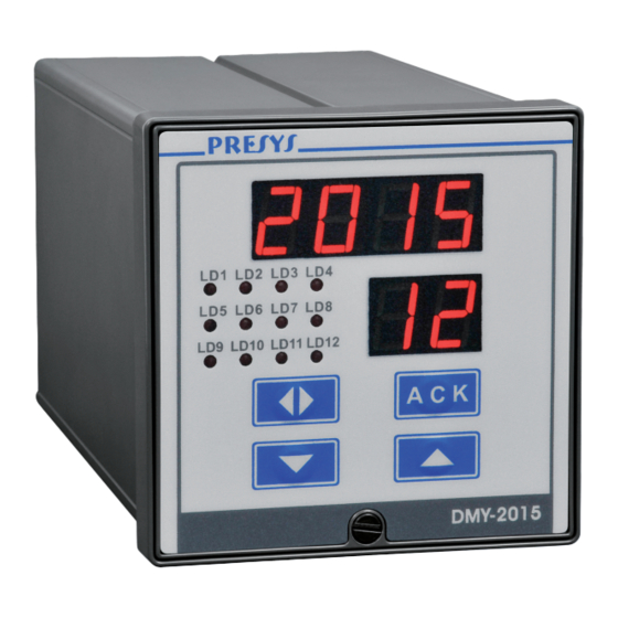
1.0 - Introduction 1.1 - Description PRESYS Digital Multi-Point Indicator DMY-2015 is a microprocessor-based instrument with up to 12 inputs for monitoring process variables found in industrial plants, such as, flow, level etc., and totalization of voltage and current linear inputs. It has non-volatile internal memory (E2PROM) to store calibration values. -
Page 5: Order Code
Presys Instruments DMY - 2015 It accepts 90 to 240VAC or 130 to 340VDC (with any polarity) power supply. The equipment has an extruded aluminum case which avoids electrical noise, electromagnetic interference, radiofrequency interference, etc. and its robust construction makes it tough enough for the most hostile environment. -
Page 6: Technical Specifications
Note 1 - The indication, relay usage as alarms and alarm points are, among other things, items that the user can program through a front key (if wanted, specify these information so that all the configuration can be made by PRESYS). Note 2 - Hardware and software features are available under previous consult. - Page 7 Presys Instruments DMY - 2015 Input sensor Measuring Range limits Thermocouple lower higher lower higher limit limit limit limit F F C C Type J -184.0 1886.0 -120.0 1030.0 Type K -346 2498 -210 1370 Type T -418 -250 Type E -148.0...
- Page 8 Presys Instruments DMY - 2015 Sampling rate: 480ms sampling rate, for indication of inputs in -999 to 9999 range. The display is updated each second. Accuracy: 0.1 % of full scale for TC, RTD, mA, VDC input. Linearization: ...
-
Page 9: Installation
2.0 - Installation 2.1 - Mechanical Installation DMY-2015 Indicator front panel has 1/4 DIN size (96 X 96 mm). It is fixed by the rails which press it against the back side of the panel. After preparing a 92 X 92 mm cut in the panel, remove the rails from the Indicator and slide its rear through the cut until its front reaches the panel. -
Page 10: Process Input Signal Connection
1, section 1.3 on Technical Specifications. The connections explained below refer to the different types of input which exist in the several models of the DMY-2015 Indicator. Make only the connections allowed by the specific inputs in your instrument. - Page 11 Presys Instruments DMY - 2015 Connect the thermocouples to the terminals shown below in table 2 for each channel: Channel Terminals 1(+) and 2(-) 3(+) and 4(-) 5(+) and 6(-) 7(+) and 8(-) 9(+) and 10(-) 11(+) and 12(-)
-
Page 12: Rtd Input
Presys Instruments DMY - 2015 2.3.2 - RTD Input Connection is allowed for 2, 3 or 4 wires RTD. All types of connection are shown in figure 5, and the connection terminals for RTD are described in table 3 below for each channel. -
Page 13: Milliampere Input
Presys Instruments DMY - 2015 An RTD input device may be a 2-wire, 3-wire or 4-wire RTD. A 2-wire RTD is connected, for example, to terminals 1 and 3 when using input 1 as shown in Figure 5. A 3-wire RTD is connected in the same way as explained for a 2-wire RTD, adding the connection of the compensation wire to terminal 2 for input 1. -
Page 14: Volt Input
Presys Instruments DMY - 2015 Figure 6 below shows the connections of current sources. Fig. 6 - Current source connection 2.3.4 - Volt Input Apply 1 to 5V voltage signal to the terminals listed in table 5 below for each... -
Page 15: Connection For Indicators With Different Input Types
Fig. 7 - Voltage source connection 2.3.5 - Connection for Indicators with different input types The available models for DMY-2015 Indicator with different types of input are listed below together with the corresponding terminals and channels for each input. The connections of the sources or temperature sensors are made according to the instructions described on sections 2.3.1 to 2.3.4. -
Page 16: Alarm Output Connection
Presys Instruments DMY - 2015 Indicator Input Terminals Type mA / V 1 and 2 (CH1), 3 and 4 (CH2), 5 and 6 (CH3), 7 and 8 (CH4), 9 and10 (CH5), 11 and 12(CH6) 13 and 14 (CH7), 15 and 16 (CH8), 17 and 18 (CH9),... -
Page 17: Connection Diagrams
Presys Instruments DMY - 2015 2.5 - Connection Diagrams 2.5.1 - Indicators with 12 thermocouples, current or voltage inputs and their combinations Installation Página 14... -
Page 18: Indicators With 8 Rtd Inputs
Presys Instruments DMY - 2015 2.5.2 - Indicators with 8 RTD inputs Installation Página 15... -
Page 19: Indicators With 6 Thermocouples, Current Or Voltage Inputs And 4 Rtd Inputs
Presys Instruments DMY - 2015 2.5.3 - Indicators with 6 thermocouples, current or voltage inputs and 4 RTD inputs Installation Página 16... -
Page 20: Communication
Presys Instruments DMY - 2015 2.6 - Communication DMY-2015 Indicator communicates with computers through RS-232 or RS- 422/485 and with use of a MODBUS protocol communication software, when the optional communication modules are installed and the communication parameters are configured. -
Page 21: Operation
DMY - 2015 3.0 - Operation 3.1 - Normal operation DMY-2015 Indicator has two modes of operation: normal mode and configuration mode. During normal operation, the Indicator monitors the inputs, verifies alarm conditions and activates the alarm outputs when necessary. - Page 22 Presys Instruments DMY - 2015 ii) To display the PASS warning, indicating that the instrument is provided with a password system (a key sequence or a value), according to figure 9. Fig. 9 - Password through key sequence or value In case of a key sequence password, the user should press the UP, DOWN and ENTER keys (exactly in this order) to access the configuration levels.
- Page 23 ENTER, UP and DOWN keys. (*) Totalization level presented only by the instruments: DMY-2015 mA, V, TC/mA, TC/V, mA/V, mA/RTD and V/RTD. Fig. 10 - Parameter levels diagram The hierarchical levels are presented in sequence. The options of each level are explained step by step with all their corresponding parameters.
- Page 24 Presys Instruments DMY - 2015 Level 1 - General Level 1 presents the options: TAG, SOFT, PASS and INDC (see figure 11). TAG - consists in an alphanumeric identification for the instrument. The procedure to enter the tag or any other parameter is the same as described previously for the password (refer to value password for the functions of the ENTER, UP and DOWN keys).
- Page 25 Presys Instruments DMY - 2015 The table below refers to the ranges of the parameters shown in figure 11. Factory Mnemonic Parameter Range Units Value instrument _______________ ____________ 2015 identification _______________ ____________ SOFT software version 1.30 ____________ VALUE user password...
- Page 26 Presys Instruments DMY - 2015 (1) IT FOLLOWS THE SAME OPTIONS OF CH-1 (2) IT FOLLOWS THE SAME OPTIONS OF CH-7 Fig. 12 - INPUT level options for Indicators with thermocouple and current inputs Operation Página 23...
- Page 27 Presys Instruments DMY - 2015 (1) IT FOLLOWS THE SAME OPTIONS OF CH-1 (2) IT FOLLOWS THE SAME OPTIONS OF CH-7 Fig. 13 - INPUT level options for Indicators with voltage and RTD inputs Operation Página 24...
- Page 28 Presys Instruments DMY - 2015 When selecting a linear sensor one must configure its scale (SCALE option). Define two points P1(Lim Low, Eng Low) and P2(Lim High, Eng High), as illustrated in figure 14. Lim Low represents the value of the electrical signal given in % of full...
- Page 29 Presys Instruments DMY - 2015 DC.PT - sets the decimal point position for visualization of Engineering units in display. There are up to three decimal places for linear signals, and for temperature sensors there is one decimal place or none.
- Page 30 Presys Instruments DMY - 2015 Fig. 16 - ALARM level options The table below refers to the ranges of the parameters shown in figure 16. Mnemonic Parameter Range Factory Value Units 25.0 - low-alarm alarm setpoint -999 to 9999 75.0 - high-alarm...
- Page 31 Presys Instruments DMY - 2015 LATCHED - configures the relay to be deactivated only after the end of the alarm condition and the operator has performed the acknowledge of this alarm. The acknowledgment of the alarm condition is performed within the normal operation mode by pressing the ACK key until it is shown the mnemonic corresponding to the relay one is looking for.
- Page 32 Presys Instruments DMY - 2015 Level 4 - Totalization In level 4, it is configured the totalization of the process variables of the first 8 channels with linear input. When the totalization of a certain channel is enabled, the indicator shows the value of the process variable and its totalization in the operation level.
- Page 33 Presys Instruments DMY - 2015 The integration function is described by: CONT E(t) ENGLOW TOTAL(t) = TIME ENGHIGH ENGLOW Notice that any signal under the input zero scale (low limit of the range or Eng Low) is not integrated, that is, the totalization does not decrease.
-
Page 34: Maintenance
Presys Instruments DMY - 2015 4.0 - Maintenance 4.1 - Indicator Hardware The Indicator maintenance requires the user to have access to the hardware of the instrument. The Indicator hardware consists of four main boards: Display Board, CPU Board, Power Supply Board and Input Board. The four-board system is fixed to the aluminum case by a screw on the lower part of the front-panel. -
Page 35: Snubber Use For Relays
Presys Instruments DMY - 2015 4.2 - Snubber use for relay Relay modules are provided with circuits for eliminating electrical arch (RC snubber). The snubbers are put in parallel with the relay contacts, by placing the jumpers J1 and J2 localized on the back of the relay board. When the jumpers are not placed, the relay contacts are kept without snubbers. -
Page 36: Optional Module Connection
DMY - 2015 4.3 - Installation of optional modules The DMY-2015 Indicator accepts up to two alarm devices and communication, which must have the corresponding optional modules installed in the instrument. Open the Indicator as shown in section 4.1 in order to access the connectors in the Power Supply Board, and one connector in the CPU Board (see figure 21). -
Page 37: Calibration
MSD - 20 Table 9 - Alarm output types 4.4 - Calibration DMY-2015 Indicator is accurately calibrated in factory and doesn’t need periodic calibration in normal conditions. When calibration is required, follow this procedure below. Disconnect the process signals of I/O terminals. - Page 38 Presys Instruments DMY - 2015 After performing all references on the table related to the input type to be calibrated, the calibration process will be finished. It is possible to calibrate only one point without rendering invalid the other points already calibrated, in case the calibration of this point was not carried out properly.
- Page 39 Presys Instruments DMY - 2015 Once the calibrations with mV are done, access the CJC mnemonic inside INPT option of level 5 for cold junction calibration. Cold junction calibration The CJC mnemonic must be accessed, which corresponds to the cold junction temperature of the Indicator.
- Page 40 Presys Instruments DMY - 2015 Calibration of current input (0 to 20mA) In a 0 to 20mA current input calibration connect a current source to the channel to be calibrated (see the terminals corresponding to each channel in table 4 on section 2.3.3 - Milliampere Input or tables 6 and 7 on section 2.3.5 - Connection...
-
Page 41: Hardware Maintenance Instructions
Presys Instruments DMY - 2015 Return to factory calibration The Indicator stores the factory calibration parameter values on the non- volatile memory, which may be always recovered by Indicators with RTD input. In case of a bad performance of the instrument due to an incorrect calibration, use the REC option. - Page 42 Presys Instruments DMY - 2015 Test points on flat cable 1 Voltage Between point 1(-) and point 2(+) Between point 9(-) and point 8(+) Between point 9(-) and point 1(+) Between point 9(-) and point 10(+) - 8V Between point 9(-) and point 13(+)
-
Page 43: List Of Components
Presys Instruments DMY - 2015 4.6 - List of components Display Board Code Components Reference 01.05.0079-20 Display Board - DMY2015 --------------------- 01.07.0002-21 Display 14mm DP1,2,3,4,5,6 01.04.0001-21 Diode 1N4002 D13,14 01.07.0005-21 Led 3mm (red) D1,2,3,4,5,6,7,8,9,10, 11,12 01.09.0013-21 Transistor BC 327 Q1,2,3,4,5,6,7,8 01.15.0003-21... - Page 44 Presys Instruments DMY - 2015 Code Components Reference 01.02.0110-21 Resistor 27K 01.02.0085-21 Resistor 47K 01.02.0106-21 Resistor 150K 5% 01.02.0088-21 Resistor 470K 5% 01.02.0006-21 Resistor 20R 01.02.0183-21 Resistor 2K32 1% 01.02.0108-21 Resistor 15K4 1% 01.02.0131-21 Resistor 4K99 5% ----------------------- 01.04.0005-21...
- Page 45 Presys Instruments DMY - 2015 Code Components Reference 01.14.0010-21 Flat Cable 15 Circuits 01.14.0030-21 Flat Cable 13 Circuits 01.14.0029-21 Flat Cable 12 Circuits 01.14.0044-21 Flat Cable 16 Circuits 01.14.0043-21 Flat Cable 13 Circuits Input Board Code Components Reference 01.05.0082-20...
-
Page 46: List Of Recommended Spare Components
Presys Instruments DMY - 2015 4.7 - List of recommended spare components Display Board Display DP1, 2, 3, 4, 5, 6 Power Supply Board IRF 822 UC 3842 Fuse 2A LM 358N I/O Terminal Board BC 337 CPU Board... - Page 47 Presys Presys | Instruments Inc. www.presys.com.br...
Need help?
Do you have a question about the DMY-2015 and is the answer not in the manual?
Questions and answers