
Related Manuals for Presys DMY-2030


Summary of Contents for Presys DMY-2030
- Page 1 PRESYS Instruments DMY-2030 Universal Process Indicator PRESYS DMY-2030 TECHNICAL MANUAL...
-
Page 2: Table Of Contents
PRESYS Instruments DMY - 2030 TABLE OF CONTENTS Page 1 - Introduction................1.1 - Description..............1.2 - Order................1.3 - Technical Specifications..........2 - Installation................2.1 - Mechanical Installation........... 2.2 - Electrical Installation............2.3 - Process Input Signal Connection........2.3.1 - Thermocouple Input.......... -
Page 3: Introduction
1 - Introduction 1.1 - Description The PRESYS DMY-2030 Indicator is an instrument based on microprocessor that shows all kind of industrial process variable, such as: temperature, pressure, flow and level. It has non-volatile internal memory (E2PROM) to store calibration values. -
Page 4: Order
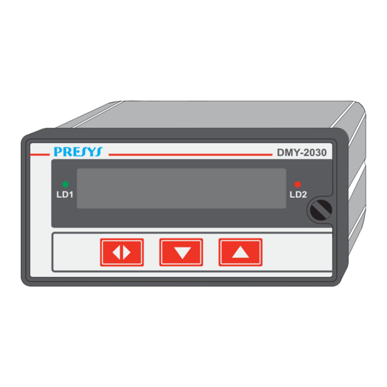
PRESYS Instruments DMY - 2030 ½ The front panel equipment has a high visibility display configurable up to 4 digits which can show parameters on channel 1, channel 2 or both. During the configuration, the display shows mnemonics and parameter values. -
Page 5: Technical Specifications
1) DMY - 2030 - 0 - 0 - 1 - 1 - 1 - 0 - 0 This code defines a DMY-2030 indicator with two SPDT relays which can be used as high and low alarm, 90-240Vac electric power supply, protected field usage. - Page 6 PRESYS Instruments DMY - 2030 Input Sensor Measuring Range Limits Thermocouple lower limit higher limit lower limit higher °F °F °C limit °C Type J -184 1886 -120 1030 Type K -346 2498 -210 1370 Type T -418 -250 Type E...
- Page 7 PRESYS Instruments DMY - 2030 Indication: 14mm red leds display with four and a half digits which can be configured together with the decimal point. Configuration: By front-panel pushbuttons and internal jumpers. Sampling rate: 100 ms Standard. One second display update rate.
-
Page 8: Installation
DMY - 2030 2 - Installation 2.1 - Mechanical Installation The DMY-2030 front panel indicator is 1/8 DIN size (48mm X 96 mm) Prepare the panel cutout according to Figure 2. Slide the instruments sleeve into the cutout from the front. -
Page 9: Process Input Signal Connection
PRESYS Instruments DMY - 2030 Make input and output terminations to instrument only with the power off. Refer to Figure 3 for rear terminal designations. Keep power and signal input separated. CAUTION: The instrument ground should be directly connected to earth ground. -
Page 10: Thermocouple Input
PRESYS Instruments DMY - 2030 2.3.1 - Thermocouple Input When there is only one thermocouple, connect it to input 1 in order to get better values in temperature measurement. Put thermal paste from the terminals of the thermocouple to the cold junction sensor in order to decrease the cold junction compensation error (only if high- accuracy is needed). -
Page 11: Milliampere Input
PRESYS Instruments DMY - 2030 Use the same material, gauge and length copper wire on all 3 terminals. The maximum resistance of connection wire is 10 Ω / wire. GROUNDED Note 1 Note 1 Note 1 Note 1 Channel 2... -
Page 12: Volt Or Millivolt Input
PRESYS Instruments DMY - 2030 2-Wire transmitter 4-Wire Transmitter Ungrounded transmitter Note 1: Shield to be left unconnected at this end. Note 2: Connect the shileld wire to the transmitter ground. If there is no ground terminal, let the shield wire disconnected at this end. - Page 13 PRESYS Instruments DMY - 2030 0 to 55 m V 0 to 55 m V 0 to 55 m V 0 to 55 m V 0 to 5V 0 to 5V 0 to 5V 0 a 5 V N o te 2...
-
Page 14: Output Connection
PRESYS Instruments DMY - 2030 Note that I/O terminals only show output signal if optional module is installed and the output is configured. Refer to Configuration - section 3.2 for further details. FUNCTION TERMINALS INTERNAL DEVICE OUTPUT 1 RETRANSMITTER OUTPUT... -
Page 15: Connection Diagrams
PRESYS Instruments DMY - 2030 2.5 - Connection Diagrams Current 4-20mA Voltage 0 to 10V Transmitter Power Supply +24V COMMUNICATION RS-422/485 Tx- Tx+ Rx- Rx+ COMMOM RS-232 INPUT 2 INPUT 1 COMMOM EARTH NEUTRAl LINE OUTPUT 4 OUTPUT 3 OUTPUT 2 OUTPUT 1... -
Page 16: Communication
PRESYS Instruments DMY - 2030 2.6 - Communication The Indicator DMY - 2030 can communicate with computers by RS-232 or RS- 422/485 since optional module is installed and the communication parameters are configured. 2.7 - Engineering Units A label containing a selection of Engineering Units is supplied with each Indicator. -
Page 17: Operation
DMY - 2030 3 - Operation 3.1 - Normal Operation The Indicator DMY-2030 has two modes of operation: normal mode and configuration mode. During normal operation, the Indicator monitors the two inputs, verifies alarm conditions and activates four outputs if necessary. - Page 18 PRESYS Instruments DMY - 2030 GENERAL PASS RIGHT WRONG OPERATION GENERAL 0000 PASS RIGHT OPERATION WRONG Figure 9 - Password by Key and by value Press UP, DOWN and ENTER Keys in this order to enter configuration level for password by Key.
- Page 19 PRESYS Instruments DMY - 2030 Warning: Rectangles mean the Indicator display in figure 10. LEVEL 6 CALIB LEVEL 5 OUTPUT LEVEL 4 ALAR LEVEL 3 INPUTS LEVEL 2 GENER LEVEL 1 GENER OPERATION LEVEL 0 PASS Figure 10 - Parameters Levels Diagram.
- Page 20 PRESYS Instruments DMY - 2030 PASSWORD - allows putting or not a password system in order to access the configuration mode. Password system can be changed by Key, value (number chosen by user or the number 2030) or both. Press UP, DOWN and ENTER Keys in this order to get password by Key.
- Page 21 PRESYS Instruments DMY - 2030 Level 2 - Inputs The level of inputs allows whether or not to enable (by means of the option CANCEL) the sensor type for input 1 and input 2. For sensor types we have the linear option (0 to 5V, 0 to 55mV and 0 to 20mA) and temperature (option TEMP), as illustrated in figure 14.
- Page 22 PRESYS Instruments DMY - 2030 Table from Figure 12. Mnemonic Parameter Span Factory Units input signal associated LIM LOW to Eng Low 0.0 to 100.0 input signal associated LIM HIGH to Eng High 0.0 to 100.0 100.0 display indication ENG LOW...
- Page 23 PRESYS Instruments DMY - 2030 SQRT - shows the input signal square root. Refer to figure 14 for further details. ENG HIGH DISPLAY VALUE ENG LOW CUT-OFF* LIM LOW * (LIM LOW + CUT-OFF)* LIM HIGH* INDICATOR INPUT SIGNAL (*) % Full-scale input signal Figure 14 - Input Signal Square Root DEC.PT - sets the decimal point for visualization of Engineering units in...
- Page 24 PRESYS Instruments DMY - 2030 Level 3 - Alarms The Indicator has up to seven alarm devices: four are the outputs 1, 2, 3 and 4 used as alarm outputs which are relay 1, relay 2, relay 3 and relay 4. The other three devices are couple of leds LED 1 and LED 2 and the display , in this case the option INDEP is selected.
- Page 25 PRESYS Instruments DMY - 2030 DELAY - it delays the relays operation. The Figure 15 shows the behavior of delay for high-alarm. Measured Variable (S1Hr3) High alarm set-point Time Delay Delay NON ALARM ALARM Figure 15 - Relay with delay.
- Page 26 PRESYS Instruments DMY - 2030 (1) SAME OPTIONS OF RELAY 1. (2) SAME OPTIONS OF LED 1. Figure 16 - ALARMS Level Options Operation Page 24...
- Page 27 PRESYS Instruments DMY - 2030 The table below shows the parameters from figure 16. Mnemonic Parameter Range Default Value Units Alarm set-point -1009 to 25.0 - low al. 20019 75.0 - high al. HYST alarm hysteresis 0 to 250 DELAY delay for activating 0.0 to 3000.0...
- Page 28 PRESYS Instruments DMY - 2030 Analog output is enabled after selecting the range of retransmission output via mnemonic RANGE. RANGE - It selects the range of retransmission output for 20mA, 5V and 10V. The ratio between the Engineering Unit and electric signal from I/O terminals is defined as linear process scale configuration.
-
Page 29: Maintenance
PRESYS Instruments DMY - 2030 4 - Maintenance 4.1 - Indicator Hardware The Indicator maintenance demands the user to have access to instrument hardware. The Indicator hardware consists of three main boards: Display Board, CPU Board and Power Supply Board. The three-board-system is fixed to aluminum case by a screw on the right side of the front-panel. -
Page 30: Hardware Configuration
PRESYS Instruments DMY - 2030 4.2 - Hardware Configuration The configuration level by software of inputs (level 2 - Inputs) must be complemented via configuration by process input hardware, through internal jumpers. There are four places for installation of jumpers into the channel 1: J5, J6, J7 and J8;... -
Page 31: Optional Module Connection
PRESYS Instruments DMY - 2030 Location for Jumpers 1 to 4 Location for Jumpers 5 to 8 Jumpers on dummy positions Figure 21 - Jumpers put in the board pin but with no use for 0 to 10V input. 4.3 - Installation of optional modules The Module Indicator can have up to four output signals and the communication module. - Page 32 PRESYS Instruments DMY - 2030 The connectors in power supply board are called MOD 1, MOD 2, MOD 3 and MOD 4, and are associated in this order with output 1, output 2, output 3 and output 4 signals, in Indicator I/O terminals as shown in Figure 3. The communication module connection is situated in CPU board.
- Page 33 PRESYS Instruments DMY - 2030 Retransmission Output Type Jumpers 4 to 20mA* 1 to 5V 0 to 10V Table 3 - Retransmission Output Type Configuration Jumper (*) In case of retransmission output in current of 4 to 20mA, one must keep the jumper out of the instrument or put it on only one connector pin without using as shown in Figure 21.
-
Page 34: Calibration
PRESYS Instruments DMY - 2030 4.4 - Calibration The DMY-2030 Indicator is accurately calibrated in factory and doesn’t need periodic recalibration in normal conditions. Follow this procedure when the instrument needs recalibration. Disconnect the process signals of I/O terminals. Apply power to the instrument and let it warm up for at least 30 minutes. - Page 35 PRESYS Instruments DMY - 2030 Figure 25 shows the options of input and output calibration for level 5 of Calibration. (1) similar to 5V (input), refer to text (2) similar to 5V (output), refer to text. (3) same options as CH-1...
- Page 36 PRESYS Instruments DMY - 2030 Input Calibration in voltage (0 to 55mV) For input calibration in voltage from 0 to 55mV connect a dc voltage source to channel to be calibrated (terminals 2(+) and 3(-) for channel 1 or 5(+) and 6(-) for channel 2).
- Page 37 PRESYS Instruments DMY - 2030 Reference Mnemonic 0.0000V C. 0V 2.0000V C. 2V 4.0000V C. 4V 6.0000V C. 6V 8.0000V C. 8V 10.0000V C.10V Table 8 - Input Calibration in Voltage from 0 to 10V Input Calibration in current (0 to 20mA)
- Page 38 PRESYS Instruments DMY - 2030 This value is the first approximation of cold junction temperature. The user must measure accurately the temperature of I/O terminals and correct the value shown by program as shown in section 3.2 of Configuration. At last the thermocouple input calibration is finished.
-
Page 39: Maintenance And Hardware Instructions
PRESYS Instruments DMY - 2030 Output Type Output 1 and Input 1 Output 2 and Input 2 current (0 to 20mA) terminal 13 (+) and 1 (+) terminal 15 (+) and 4 (+) voltage (0 to 10V) terminal 14 ( - ) and 3 ( - ) - Page 40 PRESYS Instruments DMY - 2030 Instrument shows error on display After turning on the equipment, it starts up normal tests about RAM and E2PROM. When one of these components has problems, the display shows the error code below. Err. 01 - RAM error Err.
- Page 41 PRESYS Instruments DMY - 2030 CPU BOARD POWER SUPPLY BOARD Flat-cable 1 Figure 26 - Voltage Test Points of Indicator If there is no solution for the problem, the Indicator must be sent to factory. Maintenance Page 39...
- Page 42 PRESYS INSTRUMENTOS E SISTEMAS LTDA. RUA LUIZ DA COSTA RAMOS, 260 - SAUDE SAO PAULO SP BRAZIL 9001 04157-020 - PHONE +55 (11) 5073.1900 - FAX +55 (11) 5073.3366...
Need help?
Do you have a question about the DMY-2030 and is the answer not in the manual?
Questions and answers