
Related Manuals for Presys DMY-2030-F


Summary of Contents for Presys DMY-2030-F
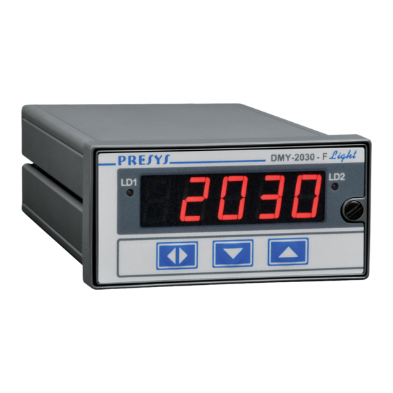
- Page 1 Empresa Nacional Tecnologia 100% Brasileira PRESYS DMY-2030-F PRESYS Light DMY-2030-F Frequency Digital Indicator DMY-2030-F / DMY-2030-F Light Technical Manual EM0136-01...
- Page 2 Presys Instruments Declaration of Conformity Presys unit DMY-2030-F and DMY-2030-F Light has been designed to comply with the following European Standards: EN 50081-1: 1992 Electromagnetic Compatibility - Generic emission standard. EN 50081-2: 1994 EN 50082-1: 1992 Electromagnetic Compatibility - Generic immunity standard.
-
Page 3: Table Of Contents
PRESYS ⏐ Instruments DMY-2030-F / DMY-2030-F Light TABLE OF CONTENTS 1.0 - Introduction ......................1 1.1 - Description.......................1 1.2 - Order Code......................2 1.3 - Technical Specifications ..................3 2.0 - Installation ......................5 2.1 - Mechanical Installation ..................5 2.2 - Electrical Installation ..................5 2.3 - Process Input Signal Connections ..............6... -
Page 4: Introduction
DMY-2030-F Light Indicator monitors one frequency input for signals of sinusoidal, squared or triangular waveforms and all pulses with amplitude between 300mV (Volt peak-to-peak) or input from contact closures. The input frequency ranges from 0Hz to 30kHz. The indication on the display is user-configurable, which allows the process variable to be shown in engineering units (rpm, Hz, etc.). -
Page 5: Order Code
4 ½ digits which can show the process variable from channel 1, channel 2 or from both channels in the scan mode for the DMY-2030-F Indicator, and only channel 1 for the DMY-2030-F Light Indicator. During configuration, the display shows mnemonics and parameter values. -
Page 6: Technical Specifications
(if wanted, specify this information so that all the configuration can be made by PRESYS). Note 2 - Other hardware and software features are available under previous consult. - Page 7 • Analog output 4 to 20 mAdc, 1 to 5 Vdc, 0 to 10 Vdc, use of optional modules with plug-in fitting for up to two modules for DMY-2030-F and one module for DMY-2030-F Light, 300 Vac galvanically isolated from inputs and power supply.
-
Page 8: Installation
DMY-2030-F / DMY-2030-F Light 2.0 - Installation 2.1 - Mechanical Installation DMY-2030-F and DMY-2030-F Light Indicators front panel has 1/8 DIN size (48 x 96 mm). They are fixed by the rails which press them against the back side of the panel. -
Page 9: Process Input Signal Connections
PRESYS ⏐ Instruments DMY-2030-F / DMY-2030-F Light Input and output signals must be connected to the instrument only when it is turned off. Figure 3 shows the instrument rear terminals for connection of power supply, ground, communication, process input and output signals. -
Page 10: Output Connection
DMY-2030-F Light output 2 is used only as alarm output. In the case of outputs 1 (in both Indicators) and 2 (in DMY-2030-F) one can have six different types of outputs: retransmitter (4 to 20mA, 0 to 5Vdc or 0 to 10Vdc), SPST relay, open collector voltage and solid state relay. - Page 11 PRESYS ⏐ Instruments DMY-2030-F / DMY-2030-F Light Note - For inductive proximity switches, connect the shield to the common terminal of the instrument (terminal 3 for input 1 and terminal 6 for input 2). Fig. 5 - Sensor connection Installation...
- Page 12 (*) Position of relay contacts when SAFE option is enabled (see section 3.2 on Configuration), the Indicator is powered on and in non-alarm condition. When the Indicator is powered off or in alarm condition with SAFE option disabled, the position of the relays changes. (**) Retransmitter output 2 only for DMY-2030-F. Fig. 6 - Output Connection Installation...
-
Page 13: Connection Diagram
PRESYS ⏐ Instruments DMY-2030-F / DMY-2030-F Light 2.5 - Connection Diagram Installation Page 10... -
Page 14: Communication
⏐ Instruments DMY-2030-F / DMY-2030-F Light 2.6 - Communication DMY-2030-F and DMY-2030-F Light Indicators communicate with computers through RS-232 or RS-422/485 when the optional communication module is installed and the communication parameters are configured. Specific information on communication and signal connection is described in the communication manual. -
Page 15: Operation
DMY-2030-F / DMY-2030-F Light 3.0 - Operation 3.1 - Normal Operation DMY-2030-F and DMY-2030-F Light Indicators have two modes of operation: normal operation and configuration mode. During normal operation, the Indicators monitor the inputs, verify alarm conditions and activate the four outputs when necessary. - Page 16 PRESYS ⏐ Instruments DMY-2030-F / DMY-2030-F Light Fig. 7 - Password through key sequence or value In case of a key sequence password, the user should press the UP, DOWN and ENTER keys (exactly in this order) to access the configuration levels.
- Page 17 PRESYS ⏐ Instruments DMY-2030-F / DMY-2030-F Light ENTER Moves into the indicated level Moves to higher levels DOWN Moves to lower levels Warning: In the diagrams below, the rectangles represent the display appearance after selection of the ENTER, UP and DOWN keys.
- Page 18 PRESYS ⏐ Instruments DMY-2030-F / DMY-2030-F Light SOFT - shows software version. PASS - allows the user to enable or disable the password system for accessing the configuration mode. The password system may be chosen as key sequence, a value (number chosen by the user and number 2030) or both.
- Page 19 PRESYS ⏐ Instruments DMY-2030-F / DMY-2030-F Light Level 2 - INPUT Level 2 - Input allows the selection of the operation range of each input (given in Hz) and the association of 2 indication values, in engineering units, to the limits of the selected range.
- Page 20 PRESYS ⏐ Instruments DMY-2030-F / DMY-2030-F Light The operation range of each input must be configured (in Hz) through Lim Low and Lim High parameters in SCALE option. Lim Low is configured with the minimum input frequency (in Hz, without decimal point) and Lim High is (generally) the maximum frequency of the range.
- Page 21 PRESYS ⏐ Instruments DMY-2030-F / DMY-2030-F Light ANNUL disables the reading of the corresponding input. In operation level, the NONE mnemonic is indicated for a disabled input. In order to enable the input to return to its normal operation, just confirm one of the parameters Lim Low, Lim High, Eng Low or Eng High in SCALE option from INPUT level.
- Page 22 PRESYS ⏐ Instruments DMY-2030-F / DMY-2030-F Light in Hz in rpm = 60 × f / N = f / N f in Hz = f / (60 × N) = f / N f in rpm For a 0 to 5000 Hz operation range from an encoder with 100 pulses per revolution and 0 to 3000.0 rpm (= 60 ×...
- Page 23 PRESYS ⏐ Instruments DMY-2030-F / DMY-2030-F Light Level 3 - Alarms The Indicators have up to seven alarm devices: four of them are the outputs 1, 2, 3 and 4 used as alarm outputs which are relay 1, relay 2, relay 3 and relay 4. The other three devices are the couple of leds, LED 1 and LED 2, and the display which can operate independently from the relays.
- Page 24 PRESYS ⏐ Instruments DMY-2030-F / DMY-2030-F Light Fig. 12 - Relay with delay SAFE - provides safety to relays. The safety condition means the relays are powered on when the instrument is on and there is no alarm condition, and the relays are powered off when in alarm condition or in case of power failure.
- Page 25 PRESYS ⏐ Instruments DMY-2030-F / DMY-2030-F Light (1) IT FOLLOWS THE SAME OPTIONS OF RELAY 1. IT FOLLOWS THE SAME OPTIONS OF LED 1. (3) ONLY FOR DMY-2030-F . Fig. 13 - ALARM level options Operation Page 22...
- Page 26 PRESYS ⏐ Instruments DMY-2030-F / DMY-2030-F Light Level 4 - Output Level 4 allows the configuration of up to two analog outputs (refer to Figure 14). (1) IT FOLLOWS THE SAME OPTIONS OF OUTPUT 2 (2) ONLY FOR DMY-2030-F Fig. 14 - OUTPUT level options The table below refers to the ranges of the parameters shown in Figure 14.
- Page 27 PRESYS ⏐ Instruments DMY-2030-F / DMY-2030-F Light RANGE - selects the range of retransmission output as 20mA, 5V or 10V. The relation between the engineering unit and electric signal generated in the terminals is defined in the same way as shown for the input scale configuration. Define two points P1 (Eng Low, Lim Low) and P2 (Eng High, Lim High) as it is illustrated in Figure 15.
-
Page 28: Maintenance
PRESYS ⏐ Instruments DMY-2030-F / DMY-2030-F Light 4.0 - Maintenance 4.1 - Indicator Hardware The Indicator maintenance requires the user to have access to the hardware of the instrument. The Indicator hardware consists of three main boards: Display Board, CPU Board and Power Supply Board. The three-board-system is fixed to the aluminum case by a screw on the right side of the front panel. -
Page 29: Hardware Configuration
PRESYS ⏐ Instruments DMY-2030-F / DMY-2030-F Light 4.2 - Hardware Configuration The software configuration level of input (level 2 - Input) must be complemented by hardware configuration, through internal jumpers. There is one selection plug-in jumper associated to each input: J1 for input 1 and J2 for input 2. -
Page 30: Optional Module Connection
In this situation, there is no need to use the snubbers and the jumpers must be removed. 4.4 - Optional Module Connection DMY-2030-F and DMY-2030-F Light Indicators accept up to four output devices and communication, which must have the corresponding optional modules installed in the instrument. - Page 31 PRESYS ⏐ Instruments DMY-2030-F / DMY-2030-F Light Plug-in of output 1 Plug-in of output 2 Plug-in of output 3 Plug-in of output 4 Plug-in of communication Power Supply Board CPU Board Fig. 19 - Optional module connectors The connectors in the Power Supply Board are called MOD 1, MOD 2, MOD 3 and MOD 4, and are associated, in this order, with the signals of output 1, output 2, output 3 and output 4 in the Indicator output terminals as shown in Figure 3.
- Page 32 PRESYS ⏐ Instruments DMY-2030-F / DMY-2030-F Light Outputs 1 and 2 as retransmitter outputs (optional module code: MSAN-20) When output 1 is required to be a retransmitter output (4 to 20mA, 1 to 5V or 0 to 10V), connect the optional analog output module in the connector called MOD 1. If another retransmitter output is needed, connect the second module in the connector called MOD 2.
-
Page 33: Calibration
Table 4 - Alarm output types for outputs 3 and 4 4.5 - Calibration The outputs of DMY-2030-F and DMY-2030-F Light Indicators are accurately calibrated in factory and do not need periodic calibration in normal conditions. There is no need for calibrating the frequency inputs because the input reading is accomplished by a microcontroller with an accurate timebase. - Page 34 PRESYS ⏐ Instruments DMY-2030-F / DMY-2030-F Light (1) IT FOLLOWS THE SAME OPTIONS OF 5V (2) ONLY FOR DMY-2030-F Fig. 22 - Calibration Level Options Once the correct password is provided, select the output to be calibrated. Choose the type of output (0 to 20 mA, 0 to 5 V or 0 to 10 V) and press ENTER.
-
Page 35: Hardware Maintenance Instructions
PRESYS ⏐ Instruments DMY-2030-F / DMY-2030-F Light 4.6 - Hardware Maintenance Instructions Before sending the instrument back to factory check the following probable causes of a malfunctioning Indicator. Instrument with error indication on display After turning the instrument on, it tests RAM and E2PROM integrity. -
Page 36: List Of Components
PRESYS ⏐ Instruments DMY-2030-F / DMY-2030-F Light Test points on flat cable 1 Voltage Between point 1(-) and point 2(+) Between point 9(-) and point 8(+) Between point 9(-) and point 1(+) Between point 9(-) and point 10(+) - 8V... - Page 37 PRESYS ⏐ Instruments DMY-2030-F / DMY-2030-F Light Power Supply Board Code Components Reference 01.05.0046-20 Power Supply Board --------------------- 01.01.0029-21 LM 2940CT - 5.0 V 01.01.0003-21 LM1458N 01.01.0030-21 UC 3842 01.09.0015-21 Transistor BC 337 01.09.0019-21 Transistor TIP 50 01.09.0020-21 IRF 822 01.02.0122-21...
- Page 38 PRESYS ⏐ Instruments DMY-2030-F / DMY-2030-F Light CPU Board Code Components Reference 01.05.0072-20 CPU board ----------------------- 01.01.0056-21 LM 392N U 3, 15 01.01.0016-21 EPROM 27C512 01.01.0017-21 RAM 6516 01.01.0044-21 E2PROM X25043 / X5043 U 19 01.01.0011-21 TC4040BP U 14, 17 01.01.0019-21...
-
Page 39: List Of Recommended Spare Components
PRESYS ⏐ Instruments DMY-2030-F / DMY-2030-F Light 01.09.0006-21 TIP 117 01.09.0015-21 Transistor BC 337 01.09.0021-21 Transistor BF 245A 01.04.0030-21 Zener Diode BZX 79/C3V3 01.04.0011-21 Zener Diode BZX79/C3V9 01.04.0005-21 Reference Diode LM 336 / 5.0 V Z 2,4 01.03.0042-21 Radial Electrolytic Capacitor 22μF x 25 V 01.03.0035-21... - Page 40 PRESYS INSTRUMENTOS E SISTEMAS LTDA. RUA LUIZ DA COSTA RAMOS, 260 - SAUDE SAO PAULO SP BRAZIL 9001 04157-020 - PHONE +55 (11) 5073.1900 - FAX +55 (11) 5073.3366...
Need help?
Do you have a question about the DMY-2030-F and is the answer not in the manual?
Questions and answers