Table of Contents
Advertisement
Quick Links
Advertisement
Table of Contents

Subscribe to Our Youtube Channel
Related Manuals for Presys DMY-2030 Light


Summary of Contents for Presys DMY-2030 Light
- Page 1 Universal Digital Indicator DMY-2030 Light 5S Energy Technical Manual EM0267-01...
- Page 2 ATTENTION! In case of failure, the instrument can provide AC voltage levels in its metal box, which for safety reasons must always be connected to an effective ground point. To this end a suitable terminal is provided on the back of the box identified as GND. Never connect this terminal to the neutral terminal of power supply.
-
Page 3: Table Of Contents
PRESYS Instruments DMY-2030-Light-5S-Energy Table of Contents 1.0 - Introduction ....................1 1.1 - Description ....................1 1.2 - Order Code ....................2 1.3 - Technical Specifications ................4 2.0 - Installation ..................... 6 2.1 - Mechanical Installation ................. 6 2.2 - Electrical Installation .................. -
Page 5: Introduction
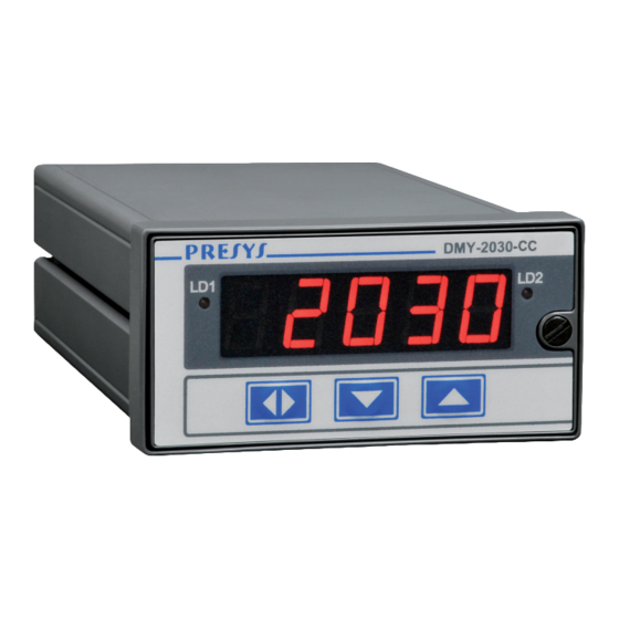
PRESYS Instruments DMY-2030-Light-5S-Energy 1.0 - Introduction 1.1 - Description The DMY-2030-Light-5S-Energy is ideal for security applications in turbines, hydroelectric plants and thermoelectric generators. It has monitoring capability of one universal standard input, accepting direct connection of RTD, thermocouple, current (mAdc) and voltage (mVdc, Vdc). The inputs RTD and thermocouple are automatically linearized by tables stored in the EPROM. -
Page 6: Order Code
PRESYS Instruments DMY-2030-Light-5S-Energy The instrument has an extruded aluminum case which makes it highly immune to electrical noise, electromagnetic interference and resistant to the most severe conditions of industrial use. 1.2 - Order Code Order Code: DMY-2030-Light-5S Field A... - Page 7 Notes 1 - The input type, the indication, the retransmitter output and the use of alarm relays are items that the user can program through the front keys (if desired, specify this information so that all programming is done by Presys). Note: Any other desired feature, software or hardware may be available upon request.
-
Page 8: Technical Specifications
PRESYS Instruments DMY-2030-Light-5S-Energy 1.3 - Technical Specifications Input: RTD Pt-100 under DIN 43760, thermocouple (J, K, T, E, R, S, under ITS-90), 4-20 mA, 0-500 mVdc, 1-5 Vdc, 0-10 Vdc. Input impedance of 250 for mA, 10 M for 5 Vdc and 2 M above 5 Vdc. The table below shows the temperature ranges for thermocouples and RTD, and the resolution for linear input sensors. - Page 9 PRESYS Instruments DMY-2030-Light-5S-Energy Linearization: 0.1 C for RTD and 0.2 C for TC. Square root extraction: 0.5 % of reading, for input above 10% of span. 0 to 5% programmable Cut-off. Cold junction compensation: ...
-
Page 10: Installation
PRESYS Instruments DMY-2030-Light-5S-Energy 2.0 - Installation 2.1 - Mechanical Installation DMY-2030-Light-5S-Energy Indicator front panel has 1/8 DIN size (48 x 96mm). It is fixed by the rails which press it against the back side of the panel. After preparing a 45 x 92 mm cut in the panel, remove the rails from the Indicator and slide its rear through the cut until its front reaches the panel. -
Page 11: Electrical Installation
PRESYS Instruments DMY-2030-Light-5S-Energy 2.2 - Electrical Installation DMY-2030-Light-5S-Energy Indicator may be powered by voltage between 75 and 264 Vac or 100 to 360 Vdc, any polarity. Remember that the internal circuit is powered whenever the instrument is connected to the external power supply. -
Page 12: Thermocouple Connections
PRESYS Instruments DMY-2030-Light-5S-Energy 2.3.1 - Thermocouple Connections Connect the thermocouple to terminals 2(+) and 3(-) as shown in figure 4. In order to reduce the error due to cold junction compensation, use thermal paste in the rear (from the terminals where the thermocouple is connected to the cold junction sensor). -
Page 13: Current Input
PRESYS Instruments DMY-2030-Light-5S-Energy 2.3.3 - Current Input The 4-20 mA current signal is applied to terminals 5(+) and 6(-). The current signal can be generated by a transmitter with an external power supply. In case of using the 24 Vdc internal voltage source from the Indicator to power a two-wire transmitter, the current is received only by terminal 5(+). -
Page 14: Voltage Inputs
PRESYS Instruments DMY-2030-Light-5S-Energy 2.3.4 - Voltage inputs 0 to 55mVdc or 0 to 5 Vdc must be applied to terminals 2 (+) and 3 (-). 0 to 10Vdc must be applied to terminals 4(+) and 6(-). The connections are shown in figure 7. - Page 15 PRESYS Instruments DMY-2030-Light-5S-Energy Fig. 8 - Output Connections The state of the relay contacts illustrated in Figure 8 assume the instrument turned off. If the power is on, the status (open or closed) depends on the SAFE setup and if the instrument is in alarm condition or not. Table 2 shows the state of the relay contacts in all conditions.
-
Page 16: Connection Diagram
PRESYS Instruments DMY-2030-Light-5S-Energy 2.5 - Connection Diagram Fig. 9 - Connections Diagram Installation Page 12... -
Page 17: Engineering Units
PRESYS Instruments DMY-2030-Light-5S-Energy 2.6 - Engineering Units A label with several Engineering Units is supplied with each Indicator. Select the one corresponding to the variable shown on the display and stick it to the front panel of the Indicator. -
Page 18: Operation
PRESYS Instruments DMY-2030-Light-5S-Energy 3.0 - Operation 3.1 - Normal Operation DMY-2030-Light-5S-Energy Indicator has two modes of operation: normal operation and configuration mode. During normal operation, the Indicator monitors the inputs, verifies alarm conditions and activates the outputs when necessary. - Page 19 PRESYS Instruments DMY-2030-Light-5S-Energy The information sequence presented on the display is shown in figure 10. Fig. 10 - Information in the operation level. The normal operation and configuration modes present a “timer” which makes the display return to the process variable, when it shows any other information and no key is pressed for 1 minute.
-
Page 20: Configuration
PRESYS Instruments DMY-2030-Light-5S-Energy 3.2 - Configuration In order to access the configuration mode the operator is required to provide a password which avoids a non-authorized person to change any critical parameters of the process. Thus, when press the ENTER key while the process variable is displayed within... - Page 21 PRESYS Instruments DMY-2030-Light-5S-Energy To enter a number for the password or any other parameter value is used indicator of the front buttons with the following functions: Function Increments the digit DOWN Decrements the digit ENTER Changes to the digit on the left All configuration parameters are stored in the non-volatile memory and determine the normal operation of the instrument.
- Page 22 PRESYS Instruments DMY-2030-Light-5S-Energy Inside each level, the front panel keys have the following functions: Function Moves the options in increasing direction Moves the options in decreasing direction DOWN Confirm or go forward in options inside a level, if the display does not show ESC.
- Page 23 PRESYS Instruments DMY-2030-Light-5S-Energy Level 1 - General Level 1 presents the options: PASS, TRIP, ALAR and ST.UP (see figure 13). PASS - allows the user to enable or disable the password system for accessing the configuration mode. The password system may be chosen as a key sequence, a value (number chosen by the user and number 2030) or both.
- Page 24 PRESYS Instruments DMY-2030-Light-5S-Energy Fig. 13 - General Level Options Operation Page 20...
- Page 25 PRESYS Instruments DMY-2030-Light-5S-Energy Level 2 - Input The input sensors, described in table 1 of section 1.3 on Technical Specifications, are configured according to the parameters of the Input level shown below: Fig. 14 - Input Level Options Operation...
- Page 26 PRESYS Instruments DMY-2030-Light-5S-Energy The table below refers to the ranges of the linear sensor input parameters shown in figure 14. Factory Mnemonic Parameter Range Units Value input signal associated to LIM LOW 0.0 to 100.0 Eng Low input signal associated to LIM HIGH 0.0 to 100.0...
- Page 27 PRESYS Instruments DMY-2030-Light-5S-Energy SQRT - allows presenting on the display the squared root of the linear input signal. The Cut-Off parameter given in % of the full scale makes input values below Cut-Off to be shown as zero scale. See figure 16.
- Page 28 PRESYS Instruments DMY-2030-Light-5S-Energy Levels 3 to 6 - Alarms The indicator can have up to four physical devices for alarms: relays 1, 2, 3 and 4. ALAR1, ALAR2, ALAR3 and ALAR4 mnemonics correspond to the configuration levels for alarms 1 to 4, respectively. The connectors on the Power Supply Board for the...
- Page 29 PRESYS Instruments DMY-2030-Light-5S-Energy the end of the break condition makes the display to alternate between the process variable indication and the RL.OUT mnemonic. In order to apply the reset, first go to the CONF mnemonic and press ENTER to display the PASS mnemonic. Then press the UP, DOWN and ENTER keys to enable the alarm.
- Page 30 PRESYS Instruments DMY-2030-Light-5S-Energy LATCH - makes each relay only again deactivate after the alarm condition has passed, with the acknowledgment of an alarm condition by the operator: pressing the UP key, when it is displayed the process variable in normal operating mode, until it reaches the desired relay, and then press ENTER.
- Page 31 PRESYS Instruments DMY-2030-Light-5S-Energy When the ALAR option is enabled in the GENERAL level, the user can review or change the alarm setpoint values in the normal operating level . The alarm setpoint mnemonics and the fail alarm mnemonics (the latter are shown only to indicate that the...
- Page 32 PRESYS Instruments DMY-2030-Light-5S-Energy Select the range of the retransmission output for 4-20 mA, 1-5 V or 0-10 V. Defining two points as shown in Figure 20. Low Eng is the display indication in engineering units associated with the scale of zero (1 V for the 5 V output, 0 V for the...
-
Page 33: Maintenance
PRESYS Instruments DMY-2030-Light-5S-Energy 4.0 - Maintenance 4.1 - Hardware The indicator maintenance requires that the user has access to the instrument hardware. The indicator hardware is divided into three main boards: Display Board, CPU Board and Power supply board. The set of the three boards is attached to the aluminum case by only one screw on the right side of the front panel. -
Page 34: Using Snubber With Relays
PRESYS Instruments DMY-2030-Light-5S-Energy 4.2 - Using snubber with relays Relay modules are provided with circuits for eliminating electrical arch (RC snubber). The snubbers can be put in parallel with the relay contacts, by placing the jumpers J1 and J2 localized on the back of the relay board. When the jumpers are not placed, the relay contacts are kept without snubbers. -
Page 35: Optional Modules Installation
PRESYS Instruments DMY-2030-Light-5S-Energy 4.3 - Optional Modules Installation The DMY-2030-Light-5S-Energy indicator can have up to four alarm outputs and one analog output. This requires that the corresponding optional modules are installed inside the unit. Open the indicator as shown in section 4.1 in order to access the four connectors on the Power Supply Board, plus a connector on the CPU board (see Figure 23). - Page 36 PRESYS Instruments DMY-2030-Light-5S-Energy COMPONENTS OPTIONAL MODULE DISPLAY Fig. 24 - Optional Modules Installation Retansmitter Output (Option Module code: MSAN-20X) To make use of retransmitter output (4-20 mA, 1-5 V or 0-10 V) connect the optional analog output module in CN1 and CN2 connectors available on the CPU board.
- Page 37 PRESYS Instruments DMY-2030-Light-5S-Energy Outputs 1 and 2 - With alarm outputs The outputs 1 and 2 work as alarms when connected to the corresponding optional module MOD1 and MOD2 slots, respectively. There are three possible types of alarm output: SPST relay, solid state relay and open collector voltage. The relationship between the alarm output type and the corresponding optional module is established in the table below.
-
Page 38: Calibration
PRESYS Instruments DMY-2030-Light-5S-Energy 4.4 - Calibration Warning: Only enter the following options after understand perfectly all steps. Otherwise, it may be necessary to return the instrument to the factory for recalibration. Calibration in this manual means adjustment. DMY-2030-Light-5S-Energy Indicator is accurately calibrated in factory and does not need periodic calibration in normal conditions. - Page 39 PRESYS Instruments DMY-2030-Light-5S-Energy Fig. 26 - Calibration Level Options Maintenance Page 35...
- Page 40 PRESYS Instruments DMY-2030-Light-5S-Energy Voltage input calibration (0 to 500 mV) To calibrate the voltage input from 0 to 500 mV connect a DC precision voltage source to terminals 2(+) and 3(-). Are required 6 voltage references listed in the table below.
- Page 41 PRESYS Instruments DMY-2030-Light-5S-Energy Reference Mnemonic 0.000 mA C. 0nA 4.000 mA C. 4nA 8.000 mA C. 8nA 12.000 mA C.12nA 16.000 mA C.16nA 20.000 mA C.20nA You can then return to normal operating mode down until the level zero.
- Page 42 PRESYS Instruments DMY-2030-Light-5S-Energy Make sure that the type of input to be used in the calibration of output is already well calibrated. Make connections listed in the table below depending on the type of output you want to calibrate.
-
Page 43: Hardware Maintenance Instructions
PRESYS Instruments DMY-2030-Light-5S-Energy 4.5 - Hardware Maintenance Instructions Before returning the instrument to the factory, check the following causes of an apparently defective indicator. Instrument with error indication on the display After turning the instrument on, it tests RAM and E2PROM integrity. - Page 44 PRESYS Instruments DMY-2030-Light-5S-Energy Fig. 27 - Voltage test points of the Indicator If the cause of the problem is not identified the indicator should be returned to the factory for repair. Maintenance Page 40...
- Page 48 www.presyscorp.com...
Need help?
Do you have a question about the DMY-2030 Light and is the answer not in the manual?
Questions and answers