Table of Contents
Advertisement
Quick Links
85MR3-R / 85MR3-RL
Item Checkup ........................................................ 8
Chapter 1 Specification ........................................... 10
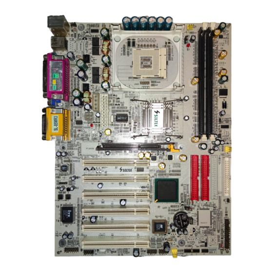
1-1 Mainboard Layout ................................................................. 11
1-2 Mainboard Specifications .................................................... 12
1-2.1 CPU Socket ................................................................................... 12
1-2.2 System Chipsets ........................................................................... 12
1-2.3 Memory ......................................................................................... 12
1-2.4 AMI BIOS ..................................................................................... 12
1-2.5 Accelerated Graphics Port (AGP) Interface ........................... 13
1-2.6 2D/3D VGA on board .................................................................. 13
1-2.7 Advanced System Power Management .................................... 13
1-2.8 Multi-I/O Functions .................................................................... 13
1-2.9 Expansion Slots ............................................................................ 14
1-2.10 LAN on board (for 85MR3-RL only) ..................................... 14
1-2.11 Hardware Monitor on board ................................................... 14
1-2.12 AC'97 Audio Codec on board .................................................. 14
1-2.13 6-channel Audio-out Support (optional) ............................... 14
1-2.14 Serial ATA RAID Controller Integrated ............................... 14
1-2.15 Form Factor ................................................................................ 15
1-3 Mainboard Specification Table ........................................... 16
1-4 Chipset System Block Diagram ........................................... 17
Chapter 2 Hardware Setup ..................................... 18
2-1 CPU Installation with Socket 478B .................................... 19
2-1.1 To Identify a Pentium 4 CPU ..................................................... 19
2-1.2 CPU Installation with Socket 478B .......................................... 20
2-2 Pentium 4 CPU Fan Installation ......................................... 21
2-3 Memory Installation ............................................................. 22
Contents
4
Advertisement
Table of Contents

Related Manuals for SOLTEK 85MR3-R


Summary of Contents for SOLTEK 85MR3-R
-
Page 1: Table Of Contents
85MR3-R / 85MR3-RL Contents Item Checkup ............8 Chapter 1 Specification ........... 10 1-1 Mainboard Layout ..............11 1-2 Mainboard Specifications ............ 12 1-2.1 CPU Socket ................... 12 1-2.2 System Chipsets ................12 1-2.3 Memory ..................12 1-2.4 AMI BIOS ..................12 1-2.5 Accelerated Graphics Port (AGP) Interface ...... - Page 2 Contents 2-3.1 To Install DDR DRAM Module ..........22 2-3.2 Indicator LED1: DIMM Powered On ........23 2-3.3 To Remove a DIMM ..............23 2-4 Install VGA / AGP4X with LED2 & Jp11 Safeguard ..24 2-5 IDE Connector Installation ..........25 2-6 Serial ATA Connector Installation ........
- Page 3 85MR3-R / 85MR3-RL 3-3 To Install “Intel Application Accelerator” ......47 3-4 To Install DirectX ..............49 3-5 To install Graphics Driver ........... 50 3-6 To Install AC’97 Audio Driver ..........51 3-6.1 Installation ................... 51 3-6.2 To verify 6-channel Audio ............52 3-7 Install Hardware Monitor Utility ........
- Page 4 Contents 4-6.7 Integrated Peripherals ..............83 4-6.8 Hardware Monitor Status ............86 4-6.9 Frequency/Voltage Control ............88 4-6.10 Set Supervisor Password ............90 4-6.11 Load Optimized Defaults ............92 4-6.12 Save & Exit Setup ..............92 4-6.13 Exit Without Saving ..............92 Chapter 5 RAID Controller ........
-
Page 5: Item Checkup
85MR3-R / 85MR3-RL Item Checkup • Mainboard • Multi-lingual Quick Installation Guide • User Manual (Mainboard) • Support CD • Bundled Bonus Pack CD • Bundled Bonus Pack Manual • Cable : ATA66/100 IDE Cable 2 x Serial ATA Cable... -
Page 6: Chapter 1 Specification
85MR3-R / 85MR3-RL Chapter 1 Specification Introduction This series of mainboards features an integration of the powerful pro- cessor Intel Pentium 4 and the single-chip North Bridge Intel 845GE. The Intel P4 processor is a rapid execution engine providing 533/... -
Page 7: Mainboard Layout
Chapter 1 Specification 1-1 Mainboard Layout LAN Controller Jp10 for 85MR3-RL only RJ45 PS/2 Mouse Fan1 (on top) PS/2 K/B (underside) RJ45 (on top) USB0 (middle) LED1 USB1 (underside) Intel Clock Generator i845GE LED2 Jp10 Jp11 AGP 4X RTL8100B PCI 1 AC'97 PCI 2 ALC650... -
Page 8: Mainboard Specifications
85MR3-R / 85MR3-RL 1-2 Mainboard Specifications 1-2.1 CPU Socket CPU Socket 478B on board, supporting Intel ® Pentium 4 processor (including Intel Hyper-Threading CPUs) in 478-pin package for : -- 533/400MHz System Bus -- Hyper-pipelined technology -- Advanced dynamic execution -- Advanced transfer cache 1-2.2 System Chipsets... -
Page 9: 1-2.5 Accelerated Graphics Port (Agp) Interface
Chapter 1 Specification 1-2.5 Accelerated Graphics Port (AGP) Interface AGP Controller embedded on board, supporting: • 1.5V(4X) power mode only • 4X AD and SBA signaling, AGP pipelined split-transaction longburst transfers up to 1GB/sec. • AGP 4X only, AGP V2.0 compliant 1-2.6 2D/3D VGA on board •... -
Page 10: 1-2.9 Expansion Slots
85MR3-R / 85MR3-RL 1-2.9 Expansion Slots • 6 PCI Bus Master slots • 1 AGP 4X slot • 2 DDR DIMM slots 1-2.10 LAN on board (for 85MR3-RL only) PCI local bus single-chip Fast Ethernet Controller RTL8100B on board: • Supporting 10/100Mb data transfer •... -
Page 11: 1-2.15 Form Factor
Chapter 1 Specification 1-2.15 Form Factor • ATX form factor, ATX power supply, version 2.03 compliant, supported by one Main Power Connector, one +12V Power Connector and one Peripheral Power Connector • Mainboard size: 305mm x 230mm... -
Page 12: Mainboard Specification Table
85MR3-R / 85MR3-RL 1-3 Mainboard Specification Table 85MR3-R/85MR3-RL Specifications and Features Socket 478B for Intel P4 CPU (HT CPU included) North Bridge Intel 845GE, supporting 533/400MHz FSB South Bridge Intel ICH4 BIOS AMI BIOS Memory Supporting DDR 333/266 DRAM, up to 2GB... -
Page 13: Chipset System Block Diagram
Chapter 1 Specification 1-4 Chipset System Block Diagram Intel Pentium 4 CPU (Hyper-Threading Included) System Bus 533/400MHz Interface DDR memory Connector Interface System Intel 845GE Memory DDR 333/ North Bridge AGP 4X 266 DRAM AGP Slot Bi-directional 2 SATA ports+ 1 IDE port 16-bit Data Bus, 266MHz PDC20376... -
Page 14: Chapter 2 Hardware Setup
85MR3-R / 85MR3-RL Chapter 2 Hardware Setup To Get Things Ready for Hardware Setup ! 1. We recommend to install your CPU before any other components. For detailed installation instructions of processor, you can also refer to the pamphlet enclosed in your CPU package. -
Page 15: Cpu Installation With Socket 478B
Chapter 2 Hardware Setup 2-1 CPU Installation with Socket 478B 2-1.1 To Identify a Pentium 4 CPU Intel pentium 4 2.4 GHz / 512 / 533 / 1.5V (Hyper-threading CPU included) 4) CPU Voltage Vcore 3) System Clock 2) CPU L2 Cache 1) CPU Working Frequency On the heatsink side of a Pentium 4 CPU, there printed a line of figures to identify its specifications. -
Page 16: 2-1.2 Cpu Installation With Socket 478B
85MR3-R / 85MR3-RL 2-1.2 CPU Installation with Socket 478B This mainboard is built with CPU Socket 478B ( 478-pin) supporting the Intel Pentium 4 CPU: • Follow the steps described in this section to install the 478-pin Pen- tium 4 CPU into the on board Socket 478. -
Page 17: Pentium 4 Cpu Fan Installation
Chapter 2 Hardware Setup 2-2 Pentium 4 CPU Fan Installation CPU Fan Connector Pentium 4 Fanbase Press down the spring locks to lock up the fan Connect to CPU Fan connector... -
Page 18: Memory Installation
85MR3-R / 85MR3-RL 2-3 Memory Installation How to tackle the memory Modules: • Make sure to unplug your power supply before adding or removing memory module. Failure to do so may cause severe damage to both your mainboard and the memory module. -
Page 19: 2-3.2 Indicator Led1: Dimm Powered On
Chapter 2 Hardware Setup 2-3.2 Indicator LED1: DIMM Powered On An indicator LED 1 is designed on board. Whenever system is started, all the DIMM slots on board will also get powered on, resulting in LED 1 lighting up. This indicator is to warn users that, whenever DIMM slot is powered, no memory module should be removed from or added onto it. -
Page 20: Install Vga / Agp4X With Led2 & Jp11 Safeguard
85MR3-R / 85MR3-RL 2-4 Install VGA / AGP4X with LED2 & Jp11 Safeguard 1. To install on-board VGA, please connect your monitor directly to VGA connector on board. Default Jp11 2-3 closed is to assure booting system with on-board VGA or 1.5V AGP4X add-on card yet without safeguard against 3.3V AGP2X card. -
Page 21: Ide Connector Installation
Chapter 2 Hardware Setup 2-5 IDE Connector Installation 1. To install IDE Connector, you may connect the blue connector of IDE cable to the primary (IDE1) or secondary (IDE2) connector on board, and then connect the gray connector to your slave device and the black connector to your master device. -
Page 22: Serial Ata Connector Installation
85MR3-R / 85MR3-RL 2-6 Serial ATA Connector Installation 2 Serial ATA connectors are built on board, supported by the Controller PDC20376. Before we install Serial ATA hard disk drive to the Serial ATA Connector, we must first enable the controller PDC20376 by Jp15 setting. -
Page 23: Floppy Drive Connector ( Fdc ) Installation
Chapter 2 Hardware Setup 2-7 Floppy Drive Connector ( FDC ) Installation To install FDC, you should connect the end of FDC cable with single connector to the board , and connect the other end with two connectors to the floppy drives. PS/2 Mouse Fan1 (on top) -
Page 24: Atx V2.03 Power Supply Installation
85MR3-R / 85MR3-RL 2-8 ATX V2.03 Power Supply Installation +12V Power Connector +12V PWR OK PS ON# PS/2 Mouse (on top) Fan1 PS/2 K/B (underside) RJ45 (on top) +3.3V -12V USB0 (middle) LED1 USB1 (underside) +3.3V +3.3V Pin1 Pin11 Main Power Connector... -
Page 25: Jumper Settings
Chapter 2 Hardware Setup 2-9 Jumper Settings The following diagrams show the locations and settings of jumper blocks on the mainboard. Jp1: KB / Mouse Power On / Wake Up CPU Clock Select (default) 1-2 closed (default) 1-2 closed KB/Mouse Power On & CPU Autodetect Wake Up Disabled 2-3 closed... -
Page 26: 2-9.1 Jp4: Cpu Clock Select
85MR3-R / 85MR3-RL How to tackle the Jumpers: A 2-pin Jumper A 3-pin Jumper If a pin-header (of 2 or more pins) is designed in such a way that its pins can be closed or linked together to The conductor inside the cap set up a specific function, this header links two header-pins together. -
Page 27: 2-9.2 Jbat1: Clear Cmos
Chapter 2 Hardware Setup Further Notes on CPU Overclocking: 1. If you have successfully booted system with or without CPU overclock, you still can do another CPU overclock in BIOS Setup. Please enter BIOS Setup, choose “Frequency/Voltage Control” menu, and take the “Use Linear”... -
Page 28: 2-9.3 Jp1: Kb / Mouse Power On / Wake Up
85MR3-R / 85MR3-RL 2-9.3 Jp1: KB / Mouse Power On / Wake Up Jp1 is a jumper for user to enable/disable the KB/Mouse Power-On or Wake-Up function. Setting Jp1 to 1-2 closed will disable this function. Setting Jp1 to 2-3 closed will enable this function, such that users can power on system (from system off) by PS/2 KB or Mouse or wake up system (from Suspend modes) either by PS/2 or USB KB/Mouse. -
Page 29: 2-9.5 Jp11: Vga/Agp 4X Safeguard
Chapter 2 Hardware Setup 2-9.5 Jp11: VGA/AGP 4X Safeguard 1. Default Jp11(2-3 closed) is to disable safeguard against 3.3V AGP2X card and allow booting system with either 1.5V on-board VGA or 1. 5V AGP4X add-on card. User can choose either VGA or AGP 4X as t h e i n i t i a l d i s p l a y b y c h a n g i n g B I O S S e t u p ( s e e “... -
Page 30: Other Connectors Configuration
85MR3-R / 85MR3-RL 2-10 Other Connectors Configuration This section lists out all connectors configurations for users’ reference. 2-10.1 On Board Fan Connectors Void Sensor PS/2 Mouse Fan1 (on top) PS/2 K/B (underside) +12V RJ45 (on top) +12V USB0 (middle) LED1 USB1 (underside) Sensor Conn. -
Page 31: 2-10.2 Usb Ports And Usb Pin-Headers
Chapter 2 Hardware Setup 2-10.2 USB Ports and USB Pin-headers This series provides two USB ports USB0 and USB1 on board sup- porting various USB devices. In addition, two USB pin-headers are added on board to provide expansion of four more optional USB ports by using two additional USB cables. -
Page 32: 2-10.3 Chassis Panel Connectors
85MR3-R / 85MR3-RL 2-10.3 Chassis Panel Connectors G : COM1 Connector A : PS/2 Mouse H : VGA Connector B : RJ45 (top) (85MR3-RL) : Line Out / C : LPT1 Port Front Speaker Out D : GAME/MIDI J : Line in/... -
Page 33: 2-10.5 Cd-Rom Audio Connectors (Cd 1)
Chapter 2 Hardware Setup 2-10.5 CD-ROM Audio Connectors (CD 1) CD 1 is an audio connector connecting CD-ROM audio to the mainboard. PS/2 Mouse Fan1 (on top) PS/2 K/B (underside) RJ45 (on top) USB0 (middle) LED1 USB1 (underside) CD-ROM Audio Connector Intel Clock Generator... -
Page 34: 2-10.7 Connector Cn19: Wake On Lan
85MR3-R / 85MR3-RL 2-10.7 Connector CN19: Wake On LAN 1. This connector connects to a LAN card with a Ring signal output. The connector powers up the system when it receives a wake-up packet or signal through the LAN card. -
Page 35: 2-10.9 Complex Pin-Header
Chapter 2 Hardware Setup 2-10.9 Complex Pin-header This complex Pin-header consists of the following connectors for vari- ous supports. When you have fixed the mainboard to the case, join the connectors of this Complex Pin-header to the case Front Panel. PS/2 Mouse (on top) Fan1... - Page 36 85MR3-R / 85MR3-RL 1. SMI Connector (System Management Interrupt): Connection: Connected to the case-mounted Suspend Switch. Function : Manually setting the DOS system into a Suspend mode or “Green” mode by System Management Interrupt. 2. Power Switch Connector: Connection: Connected to a momentary button or switch.
-
Page 37: 2-10.10 Thermal Resistor And Connector: Rt2 And Jp14
Chapter 2 Hardware Setup 2-10.10 Thermal Resistor and Connector: RT2 and Jp14 PS/2 Mouse (on top) Fan1 PS/2 K/B (underside) RJ45 (on top) USB0 (middle) LED1 USB1 (underside) RT2 is mounted with Thermal Resistor Intel by default. Clock Generator i845GE LED2 Jp10 Jp11... -
Page 38: 2-10.11 Lan Connector (85Mr3-Rl Only)
85MR3-R / 85MR3-RL 2-10.11 LAN Connector (85MR3-RL Only) One RJ45 connector is on board for network connection. Green LED blinks to indicate Yellow LED “On” to indicate that data transmission is Network hub is in connection undergoing in 10/100 Base T with the system. -
Page 39: Chapter 3 Software Setup
85MR3-R / 85MR3-RL Chapter 3 Software Setup Drivers, Utilities and Software Installation • Support CD: This series of mainboards will be shipped with a Support CD which contains those necessary driver files, Application Softwares and some helpful utilities. It is a user-friendly, auto-run CD which will open itself up in a CD-ROM automatically. -
Page 40: To Open Up The Support Cd
Chapter 3 Software Setup 3-1 To Open up the Support CD 1. Please put the Support CD enclosed in your mainboard package into the CD-ROM drive. In a few seconds, the Main Menu will automatic- ally appear, displaying the contents to be installed for this series: 2. -
Page 41: To Install "Intel Chipset Software Installation Utility
85MR3-R / 85MR3-RL 3-2 To Install “Intel Chipset Software Installation Utility” 1. Following the procedures of opening the Support CD, click to “ Install Intel Chipset software installation Utility” to proceed. 2. The Intel Service Pack InstallShield Wizard will pop up to guide you to the Intel Service pack installation. -
Page 42: To Install "Intel Application Accelerator
Chapter 3 Software Setup 3-3 To Install “Intel Application Accelerator” IAA supports all Windows 98/98SE/ME/NT4/2000/XP with Pentium III / 4 processor. Installations of this software for these operating systems are similarly programed to an auto-run mode, and it is typically designed to improve performance of the storage sub-system and overall system performance. - Page 43 85MR3-R / 85MR3-RL 4. On ”Choose Destination Location” screen, press “Next” to continue. C:\Program Files\Intel\Intel Application Accelerator k É ñ í 5. On ”InstallShield Wizard Complete” screen, choose Yes, I want to restart my computer “Yes, I want to restart my computer now”...
-
Page 44: To Install Directx
Chapter 3 Software Setup 3-4 To Install DirectX Following the installation of IAA, you have to restart system so that your system can be reconfigured with the driver just installed. When restarting procedures finish, please open the Support CD with your CD- ROM to enter the Main Installation Menu. -
Page 45: To Install Graphics Driver
85MR3-R / 85MR3-RL 3-5 To install Graphics Driver Following the installation of DirectX, you have to restart system so that your system can be reconfigured with the utility. When restarting pro- cedures finish, please open the Support CD with your CD-ROM to en- ter the Main Installation Menu. -
Page 46: To Install Ac'97 Audio Driver
Chapter 3 Software Setup 3-6 To Install AC’97 Audio Driver Avance AC97 Audio Codec on board, AC’97 2.2 compatible, supporting 6 channel audio code for PC multimedia systems. Avance AC’97 Audio Codec Driver is provided in Support CD for user’s installation. 3-6.1 Installation 1. -
Page 47: 3-6.2 To Verify 6-Channel Audio
85MR3-R / 85MR3-RL 3-6.2 To verify 6-channel Audio After installation of AC’97 6-channel Codec, you must configure the 5.1 Speaker connection to enable the 6-channel audio. 1. Connect your on-board Audio Connector to your 6-channel speakers as depicted in the figure below:... - Page 48 Chapter 3 Software Setup 3. The AC’97 Audio Configuration” screen will pop out. Click the “Speaker Configuration” bar with your mouse. 4. Instantly, the “Speaker Configuration” screen will pop out. Pick the items “6-channel mode for 5.1 speakers output” and “ Synchronize the phonejack switch with the speakers settings”...
- Page 49 85MR3-R / 85MR3-RL 5. At finishing the Speaker Configuration, you can also click the “Speaker Test” bar on the screen to test the 6-channel performance. The figure below is the “Speaker Test” screen with testing instructions enclosed on it. Follow the instructions to perform the Speakers Test.
-
Page 50: Install Hardware Monitor Utility
Chapter 3 Software Setup 3-7 Install Hardware Monitor Utility 3-7.1 Installation Hardware Monitor is built in chip IT8712F of this series. Its installa- tion is programed to a fully automated mode on Windows 9X/Me/NT4/ 2000/XP. User can follow the model installation below for its installa- tion on various Windows System. -
Page 51: 3-7.2 Verification
85MR3-R / 85MR3-RL 3-7.2 Verification 1. After restarting your computer, click “Start” and choose the path \ P r o g r a m s \ I T E S m a r t Accessories\ITE Smart Guardian to open the main window of the Hardware Doctor. -
Page 52: Install Lan Drivers (For 85Mr3-Rl Only)
Chapter 3 Software Setup 3-8 Install LAN Drivers (for 85MR3-RL only) 3-8-1. RTL8100B LAN driver on Windows 9X The LAN driver contained in the Support CD is not included in the Autorun Menu. To install RTL8100B LAN driver on Windows 9X, please follow the steps shown below: 1. - Page 53 85MR3-R / 85MR3-RL 5. In the “Update device Driver Wizard” screen, click “Next” to continue until you see a dialog box asking you to “Specify a location” for the driver. You should now insert the Support CD into your CD-ROM.
-
Page 54: Rtl8100B Lan Driver On Windows Nt4.0
Chapter 3 Software Setup 3-8-2. RTL8100B LAN driver on Windows NT4.0 1. When you newly install Win NT4, the Setup program will ask you whether your computer will participate on a network. please check “Do not connect this computer to a network at this time” and continue with your installation. -
Page 55: Rtl8100B Lan Driver On Win Me / 2000 / Xp
85MR3-R / 85MR3-RL 10. To verify that the onboard RTL8100B Controller has been set up in system, please click “Start”, then “Control Panel”, then “Network”. 11. In the “Network” screen, click the “Adapter” bar. You can now see the “Realtek RTL8139(A/B/C/8130) PCI Fast Ethernet Adapter is already installed in system. -
Page 56: To Install Usb 2.0 Driver For Win2000 Or Winxp
Chapter 3 Software Setup 3-9 To Install USB 2.0 Driver for Win2000 or WinXP USB V2.0 with its 480Mb/s transfer rate supports operating system Win2000 and WinXP with Intel USB drivers and Microsoft USB drivers. USB Driver installation procedures are of similar steps in Win2000 and WinXP. - Page 57 85MR3-R / 85MR3-RL 7. When a dialog box pops out, asking user to key in the correct path for Intel_USB2.0 driver, please type the following path and mouse click “OK” button to install the Intel_USB 2.0 driver: For both Win2000 and Win XP:...
-
Page 58: Install Raid Controller Pdc20376 Drivers
Chapter 3 Software Setup 3-9 Install RAID Controller PDC20376 Drivers 1. Please locate the Promise RAID Controller on your mainboard to make sure that you are using the right board. 2. Locate the RAID Controller Select Jumper JP15 on board, and make sure this Jumper is set at Pin 1-2 closed for enabling RAID controller. -
Page 59: Chapter 4 Ami Bios Setup
85MR3-R / 85MR3-RL Chapter 4 AMI BIOS Setup THE BIOS BIOS stands for Basic Input and Output System. It was once called ROM BIOS when it was stored in a Read-Only Memory (ROM) chip Now manufacturers would like to store BIOS in EEPROM which means Electrically Erasable Programmable Memory. -
Page 60: About Bios Setup
Chapter 4 BIOS Setup 4-1 About BIOS Setup BIOS setup is an interactive BIOS program that you need to run when: 1. Changing the hardware of your system. (For example: installing a new Hard Disk etc.) 2. Modifying the behavior of your computer. (For example: changing the system time or date, or turning special features on or off etc.) 3. -
Page 61: To Update Bios
85MR3-R / 85MR3-RL 4-5 To Update BIOS • System BIOS is incorporated into a Flash memory component. Flash BIOS allows user to upgrade BIOS without the need to replace an EPROM component. • The Upgrade Utility can be loaded on a floppy diskette for upgrading saving, and verifying the system BIOS. - Page 62 Chapter 4 BIOS Setup Step 4. Under “ A “ prompt, type “ AMIXXX.EXE *.ROM “ and then press <Enter> to run BIOS update program. Please note that there should be a space between AMIXXX.EXE and *.ROM. (*.ROM depends on your mainboard model and version code. Instead of typing “*”, you should type the specific file name for your specific mainboard).
-
Page 63: Bios Setup
85MR3-R / 85MR3-RL 4-6 BIOS SETUP --- CMOS Setup Utility 4-6.1 CMOS Setup Utility This mainboard comes with the AMI BIOS from American Megatrends Inc. Enter the CMOS Setup Utility Main Menu by: 1. Turn on or reboot your system. After a series of diagnostic checks, the following message will appear: PRESS <Del>... -
Page 64: 4-6.2 Standard Cmos Setup
Chapter 4 BIOS Setup 4-6.2 Standard CMOS Setup Standard CMOS Setup records some basic system hardware configuration and sets the system clock and error handling. Modify the configuration values of this option if you want to change your system hardware configuration or after you clear CMOS data. Run the Standard CMOS Setup as follows: 1. - Page 65 85MR3-R / 85MR3-RL System Time The BIOS shows the time of the day in the format: hh:mm:ss. Choose the field with the Arrow keys and change the time with the Page Up/Page Down +/- keys. System Date The BIOS shows the date of the day in the format: mm:dd:yy :day of the Week.
- Page 66 Chapter 4 BIOS Setup Type This option shows the types of configuration for the IDE devices: 1-50: Predefined types USER: set Parameters by User Auto: Set parameters automatically CD-ROM: Use for ATAPI CD-ROM drives Double click [Auto] to set all HDD parameters automatically, including “Cylinders, Heads, Write Precompensation, Sectors, Maximum Capacity and 32 Bit Transfer Mode.
-
Page 67: 4-6.3 Advanced Bios Features
85MR3-R / 85MR3-RL 4-6.3 Advanced BIOS Features Advanced BIOS Features improves your system performance or sets up system features according to your preference. Run the Advanced BIOS Features as follows: 1. Choose “Advanced BIOS Features” from the Main Menu and a screen with a list of options will appear: AMIBIOS NEW SETUP UTILITY - VERSION 3.31a... - Page 68 Chapter 4 BIOS Setup 2. Use one of the arrow keys to move between options and modify the selected options by using PgUp / PgDn / + / - keys. An explanation of the <F> keys follows: <F1>: “Help” gives options available for each item. <F9>: Setup BIOS default values.
- Page 69 85MR3-R / 85MR3-RL Bootup Num-lock Allows you to toggle between On or Off to control the state of the NumLock keys when the system boots. If On, the numeric keypad is in numeric mode. If off, the numeric keypad is in cursor con- trol mode.
-
Page 70: 4-6.4 Advanced Chipset Features
Chapter 4 BIOS Setup 4-6.4 Advanced Chipset Features Advanced Chipset Features is used to modify the values of chipset buffers. These buffers control the system options. Run the Advanced Chipset Features as follows: 1. Choose “Advanced Chipset Features” from the Main Menu and a list of option will appear: AMIBIOS NEW SETUP UTILITY - VERSION 3.31a Advanced Chipset Features... - Page 71 85MR3-R / 85MR3-RL SDRAM Frequency Allows you to set the SDRAM frequency. Choicesfor 100MHz CPU: Auto; 200MHz; 266MHz Choices for 133MHz CPU: Auto; 200MHz;266MHz; 333MHz Configure SDRAM SPD (Serial presence detect) is a device in memory Timing by SPD module for storing the module information such as DRAM timing and chip parameters.
- Page 72 Chapter 4 BIOS Setup Memory Hole Allows you to enabled / disabled (default) the sup- port of Memory Hole which is reserved for ISA card. (Hyper-Threading If Hyper-Threading CPU is running on board, this Function) item appears to show the enabled status. Choices: Enabled;...
-
Page 73: 4-6.5 Power Management Features
85MR3-R / 85MR3-RL 4-6.5 Power Management Features Power Management Features allows you to set the system’s power saving functions. Run the Power Management Features as follows: 1. Choose “Power Management Features” from the Main Menu and a list of options will appear: AMIBIOS NEW SETUP UTILITY - VERSION 3.31a... - Page 74 Chapter 4 BIOS Setup ACPI Standby State This item allows you to select the ACPI Suspend type. You can select S3(STR) for suspending to DRAM if your system supports this mode. Or you can select S1 (POS) for Power on Suspend under ACPI mode.
- Page 75 85MR3-R / 85MR3-RL Resume on PME# Allows you to enable / disable the Resume on PME function. Resume On RTC Alarm Allows you to enable / disable the Resume On RTC Alarm function. RTC Alarm Date / Hour If resume On RTC Alarm is enabled, this field al-...
-
Page 76: 4-6.6 Pnp / Pci Configurations
Chapter 4 BIOS Setup 4-6.6 PNP / PCI Configurations PNP/PCI Configuration allows you to modify the system’s power saving functions. Run the PNP/PCI Configurations as follows: 1. Choose “PNP/PCI Configurations” from the Main Menu and a screen with a list of options will appear: AMIBIOS NEW SETUP UTILITY - VERSION 3.31a PNP/PCI Configurations Setup Help... - Page 77 85MR3-R / 85MR3-RL Clear NVRAM Allows BIOS to clear the NVRAM data. Choices: No (default); Yes PCI Latency Timer (PCI Allows you to set the PCI Latency Time. Clocks) Choices: 32; 64; 96; 192; 128; 160; 192; 224; 248; Init. Graphics Adapter Allows you to select the initial Graphics Adapter.
-
Page 78: 4-6.7 Integrated Peripherals
Chapter 4 BIOS Setup 4-6.7 Integrated Peripherals Integrated Peripherals option allows you to get some information inside your system when it is working. Run the Integrated Peripherals as follows: 1. Choose “Integrated Peripherals” from the Main Menu and a list of options will appear: AMIBIOS NEW SETUP UTILITY - VERSION 3.31a Integrated Peripherals... - Page 79 85MR3-R / 85MR3-RL Onboard IDE Allows you to choose the Onboard IDE Mode. Choices: Disabled; Primary; Secondary; Both If this option is on board, this item allows you to en- (Optional) Onboard able / disable the onboard LAN. Choices: Enabled; Disabled Onboard AC‘97 Audio Allows you to disable AC’...
- Page 80 Chapter 4 BIOS Setup OnBoard MIDI Port Allows you to configure onboard MIDI port address. The choices: Disabled; 300h; 330h MIDI Port IRQ If the onboard MIDI port is set at 300h or 330h, this item shows up to allow you to configure the MIDI Port IRQ3 to IRQ11.
-
Page 81: 4-6.8 Hardware Monitor Status
85MR3-R / 85MR3-RL 4-6.8 Hardware Monitor Status This menu helps you to read only and get more information on the working CPU temperature, FAN speed and voltage. 1. Choose “Hardware Monitor Status” from the Main Menu and a screen with a list of current status of your working system will appear: AMIBIOS EASY SETUP UTILITY - VERSION 3.31a... - Page 82 Chapter 4 BIOS Setup Temperature 1 Shows current CPU internal temperature. Temperature 2 Shows current CPU external temperature. Temperature 3 Shows current system temperature. Fan 1 / 2 /3 Displays the current speed of CPU Fan, and other two onboard devices which user has connected to the onboard Fan Connectors.
-
Page 83: 4-6.9 Frequency/Voltage Control
85MR3-R / 85MR3-RL 4-6.9 Frequency/Voltage Control Run the “Frequency/Voltage Control” as following: 1. Choose “Frequency/Voltage Control” from the Main Menu and a screen with a list of options will appear: AMIBIOS EASY SETUP UTILITY - VERSION 3.31a Frequency/Voltage Control Setup Help... - Page 84 Chapter 4 BIOS Setup (Optional) RedStorm Press <Enter> to start RED STORM OVERCLOCK- Overclocking Tech ING TECH. This option gives user an easy way to overclocking. It will increase CPU external clock automatically. When CPU external clock increases to an unacceptably high value, BIOS will restart your system, then running at an acceptable CPU exter- nal clock.
-
Page 85: 4-6.10 Set Supervisor Password
85MR3-R / 85MR3-RL 4-6.10 Set Supervisor Password This option allows you to set a Supervisor password for the system: 1. Choose “Set Supervisor Password” in the Main Menu and press <Enter>. Then the following message appears: [ Enter new supervisor password ] 2. - Page 86 Chapter 4 BIOS Setup 8. To change or remove a current supervisor password, choose “Set Supervisor Password” and press <Enter>. An instruction box appears on the screen, prompting you to enter the current password first: [ Enter current supervisor password ] 9.
-
Page 87: 4-6.11 Load Optimized Defaults
85MR3-R / 85MR3-RL 4-6.11 Load Optimized Defaults When you press <Enter> on this item, you will get a confirmation dialog box with a message similar to: [ Load Optimized Defaults ] Press [Enter] to continue or [ESC] to abort Press <Enter> now to load Optimal values for all the Setup options. -
Page 88: Chapter 5 Raid Controller
85MR3-R / 85MR3-RL Chapter 5 RAID Controller The following topics and Appendices are included in this chapter: 5-0 Before Creating Disk Array 5-1 Creating your Disk Array 5-2 Installing RAID Controller PDC20376 Driver... -
Page 89: Before Creating Disk Array
Chapter 5 RAID Controller 5-0 Before Creating Disk Array: 1. Please locate the Promise RAID Controller on your mainboard to make sure that you are using the right board. 2. Locate the RAID Controller Select Jumper Jp15 on board, and make sure this Jumper is set at Pin 1-2 closed for enabling RAID controller. -
Page 90: Creating Your Disk Array
85MR3-R / 85MR3-RL 5-1 Creating Your Disk Array To create your disk array, you have to open the FastBuild Utility, which should have already been built in the Promise Controller. At booting your system, you will see the following initializing screen: FastTrak 376(tm) BIOS Version xxxxxx (c) 2--2-2005 Promise Technology, Inc. - Page 91 Chapter 5 RAID Controller 2. Press <Ctrl-F> keys to display the FastBuild (tm) Utility Main Menu. Auto Setup ..........[ 1 ] View Drive Assignment ......[ 2 ] Define Array .........[ 3 ] Delete Array .........[ 4 ] Rebuild Array ........[ 5 ] 3.
-
Page 92: 5-1.2 Creating Security Array With Existing Data Drive
85MR3-R / 85MR3-RL 5-1.2 Creating Security Array With Existing Data Drive FastTrak 376 on board permits only two drives to be used for a single Mirroring (Security) array with FastBuild Utility. Checkpoints before creating a Security Array: (1) You may use a drive that is containing data or a bootable O/S. - Page 93 Chapter 5 RAID Controller 3. Press “1” to display the Auto Setup Menu below. This is the fastest and easiest method to create your first array. [Auto Setup Options Menu] Optimize Array for: Performance [Array Setup Configuration] Mode ..........Stripe Spare Drive ..........0 Drives used in Array ........1 Array Disk Capacity ......38166...
-
Page 94: Installing Drivers
85MR3-R / 85MR3-RL 5-2 Installing Drivers This section details the PDC 20376 FastTrak 376 driver installation for various operating systems. The driver should have been included ei- ther into the Support CD or into a Support Floppy Diskette. Checkpoints for the driver installation: 1. - Page 95 Chapter 5 RAID Controller Note: If you need to specify any additional devices to be installed, do so at this time. Once all devices are specified, continue to step 7. 7. From the Win 2000/XP Setup screen, press the Enter key. Setup will now load all device files and then continue the Win 2000/XP installation.
-
Page 96: 5-2.2 Windows 95/98
85MR3-R / 85MR3-RL 5-2.1-3 Confirming Windows 2000 Installation 1. From Windows 2000, open the Control Panel from “ My Computer” followed by the System icon. 2. Choose the “Hardware” tab, then click the “Device Manager” tab. 3. Click the “+” in front of “SCSI & RAID Controllers hardware type.” The driver “Win2000 Promise FastTrak/FastTrak 376 Controller”... - Page 97 Chapter 5 RAID Controller 11. Insert the “FastTrak 376 Driver” diskette into the A: drive. 12. Press the “Next” button. A message informing you that Windows 98 has found “Win95-98 Promise FastTrak 376 (tm) Controller” should appear. 13. Press “Next,” then “Finish,” then “Yes” when asked if you want to restart your computer.
- Page 98 85MR3-R / 85MR3-RL 5-2.2-4 Installing Drivers With Existing Windows 95/98 The following three sections detail the installation of the FastTrak 376 drivers on a system that has Windows 95/98 already installed. If you’re installing the FastTrak 376 drivers on a system during a Windows 95/98 installation, see “Installing Drivers During Windows 95/98 Installation”.
-
Page 99: 5-2.3 Dos/Windows 3.1X
Chapter 5 RAID Controller 7. Choose “Yes” when asked whether you want to start your computer. Be sure to remove the diskette from drive A. 5-2.2-7 Confirming Driver Installation in Windows 98/95 To confirm that the driver has been properly loaded in Win 95/98, perform the following steps: 1. -
Page 100: 5-2.4 Windows Nt4.0
85MR3-R / 85MR3-RL 5-2.4 Windows NT4.0 5-2.4-1 Installing Drivers During Windows NT 4.0 Installation 1. Connect your hard drive(s) for RAID Array to IDE3/ATA1/ATA2, and enable FastTrak 376 Controller with Jp15. Start the system installation by booting from the Windows NT disk: a) Floppy install: boot the system with the Windows NT installation diskettes. - Page 101 Chapter 5 RAID Controller 5-2.4-2 Installing Drivers With Existing Windows NT4.0 W A R N I N G : W A R N I N G : Your must first complete installing the driver before moving the boot drive containing the existing Windows 2000 operating system on to the FastTrak 376 controller (e.g.
Need help?
Do you have a question about the 85MR3-R and is the answer not in the manual?
Questions and answers