Table of Contents
Advertisement
Quick Links
85ERV / 85ERV-L
Chapter 1 Specification ............................................. 9
1-1 85ERV / 85ERV-L Components and Options ................... 10
1-2 Mainboard Specifications ..................................................... 11
1-2.1 CPU Socket ................................................................................... 11
1-2.2 System Chipsets ........................................................................... 11
1-2.3 Memory ......................................................................................... 11
1-2.4 AMI BIOS ..................................................................................... 11
1-2.5 Accelerated Graphics Port (AGP) Interface ........................... 11
1-2.6 Advanced System Power Management: ................................... 12
1-2.7 Multi-I/O Functions : .................................................................. 12
1-2.8 Expansion Slots ............................................................................ 12
1-2.9 AC'97 Audio Codec on board .................................................... 13
1-2.10 LAN on board (85ERV-L only) ............................................... 13
1-2.11 Hardware Monitor on board ................................................... 13
1-2.12 6-channel Sound Output Support (optional) ........................ 13
1-2.13 Form Factor ................................................................................ 13
1-3 Mainboard Specification Table ........................................... 14
1-4 Chipset System Block Diagram ........................................... 15
Chapter 2 Hardware Setup ..................................... 16
2-1 CPU Installation with Socket 478B .................................... 17
2-2 Pentium 4 CPU Fan Installation ......................................... 18
2-3 Memory Installation with Warning LED .......................... 19
2-3.1 To Install DDR SDRAM Module for this series ..................... 19
2-3.2 To Remove a DIMM .................................................................... 19
2-4 AGP 4X/8X Slot Installation ................................................ 20
2-5 IDE Connector Installation ................................................. 21
Contents
4
Advertisement
Table of Contents

Related Manuals for SOLTEK 85ERV


Summary of Contents for SOLTEK 85ERV
-
Page 1: Table Of Contents
85ERV / 85ERV-L Contents Chapter 1 Specification ..........9 1-1 85ERV / 85ERV-L Components and Options ....10 1-2 Mainboard Specifications ............. 11 1-2.1 CPU Socket ................... 11 1-2.2 System Chipsets ................11 1-2.3 Memory ..................11 1-2.4 AMI BIOS ..................11 1-2.5 Accelerated Graphics Port (AGP) Interface ...... - Page 2 3-4 Install USB 2.0 Driver for Win98 / Me / 2000 / XP ..43 3-5 Install Hardware Monitor Utility ........45 3-5.1 Installation ................... 45 3-5.2 Verification .................. 46 3-6 Install VIA LAN Drivers (for 85ERV-L only) ....47...
- Page 3 85ERV / 85ERV-L 3-6-1. VIA6183 LAN driver on Windows 9X ........47 3-6-2. VIA6183 LAN driver on Windows NT4.0 ......49 3-6-3. VIA6183 LAN driver on Win ME / 2000 / XP ....... 50 Chapter 4 AMI BIOS Setup ........52 4-1 About BIOS Setup ..............
-
Page 4: Chapter 1 Specification
Chapter 1 Specification Chapter 1 Specification Introduction This series of mainboards features an integration of the powerful processor Intel Pentium 4 and the single-chip North Bridge VIA Apollo P4X400 plus South Bridge VT8235, by which the whole system perfor- mance can be upgraded to 533 MHz system bus. The Intel P4 processor is a rapid execution engine providing 4X100/ 4X133MHz quadpumped system bus to allow 3.2GB data transfer rates possible, while VIA Apollo P4X400 plus VT8235 supports Intel P4 pro-... -
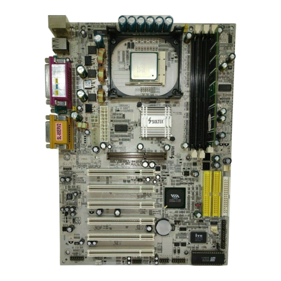
Page 5: 85Erv / 85Erv-L Components And Options
85ERV / 85ERV-L 1-1 85ERV / 85ERV-L Components and Options RJ45 for 85ERV-L only PHY LAN Controller PS/2 Mouse (on top) PS/2 K/B (underside) Rj 45 (on top) USB0 (middle) USB1 (underside) Main Power Connector P4x400 Peripheral Power AGP 4X/8X... -
Page 6: Mainboard Specifications
Chapter 1 Specification 1-2 Mainboard Specifications 1-2.1 CPU Socket ® CPU Socket 478B on board, supporting Intel Pentium 4 processors in 478-pin package for : -- 533/400MHz System Bus; -- Hyper-pipelined technology; -- Advanced dynamic execution; -- Advanced transfer cache; 1-2.2 System Chipsets •... -
Page 7: 1-2.6 Advanced System Power Management
85ERV / 85ERV-L 1-2.6 Advanced System Power Management: • ACPI 1.0B compliant (Advanced Configuration and Power Interface) • APM V1.2 compliant (Legacy Power Management) • ACPI POS (Power On Suspend) • PS/2 Keyboard & Mouse Power On • Supporting Ring Power Up Control for Wake-on-Modem (external) and Wake-on-LAN (via Connector WOL1) •... -
Page 8: 1-2.9 Ac'97 Audio Codec On Board
Right, Center and Woofer for complete surrround sound effect • AC’97 Audio Codec Driver enclosed in Support CD for user ’s installation. 1-2.10 LAN on board (85ERV-L only) Fast Ethernet Controller integrated in VT8235 and PHY VIA VT6103: • Supporting 10/100Mb Fast Ethernet Base T LAN •... -
Page 9: Mainboard Specification Table
85ERV / 85ERV-L 1-3 Mainboard Specification Table SL-85ERV / 85ERV-L Specifications and Features Socket 478B for Intel Pentium 4 CPUs North Bridge VIA Apollo P4X400, supporting 533/400MHz FSB South Bridge VIA VT8235 BIOS AwardBIOS Memory Supporting DDR 333/266/200 SDRM, up to 3GB... -
Page 10: Chipset System Block Diagram
533/400 MHz FSB P4x400 DDR 333/266/200 Memory Bus AGP 4X/8X Bus Slot North Bridge SDRAMs Double Speed (533MB/sec) V-Link (85ERV-L only) BIOS 10/100 Base T LAN Fast Ethernet Interface SM Bus PHY(VT6103) PCI Bus Game Port 6 PCI Slots VT8235... -
Page 11: Chapter 2 Hardware Setup
85ERV / 85ERV-L Chapter 2 Hardware Setup To Get things ready for hardware setup ! 1. We recommend to install your CPU before any other components. For detailed installation instructions of processor, you can also refer to the pamphlet enclosed in your CPU package. -
Page 12: Cpu Installation With Socket 478B
Chapter 2 Hardware Setup 2-1 CPU Installation with Socket 478B This series is built with CPU Socket 478B ( 478-pin) supporting the Intel Pentium 4 CPU: • Follow the steps described in this section to install the 478-pin Pen- tium 4 CPU into the on board Socket 478. •... -
Page 13: Pentium 4 Cpu Fan Installation
85ERV / 85ERV-L 2-2 Pentium 4 CPU Fan Installation Pentium 4 Fanbase CPU Fan Connector Press down 4 corners to lock fan to fanbase Connect Fan Connector to CPU FAN connector... -
Page 14: Memory Installation With Warning Led
Chapter 2 Hardware Setup 2-3 Memory Installation with Warning LED How to tackle with the memory Modules: • Make sure to unplug your power supply before adding or removing memory module. Failure to do so may cause severe damage to both your mainboard and the memory module. -
Page 15: Agp 4X/8X Slot Installation
85ERV / 85ERV-L 2-4 AGP 4X/8X Slot Installation The AGP slot on board supports 1.5V AGP4X/8X card only. A Rib is specifically added to the 4X/8X AGP slot so as to match the AGP 4X/8X card. To insert a 3.3V AGP 2X card into the AGP 4X slot will damage the system chip and burn the 1.5V circuitry. -
Page 16: Ide Connector Installation
Chapter 2 Hardware Setup 2-5 IDE Connector Installation To install IDE Connector, you may connect the blue connector of IDE cable to the primary (IDE1) or secondary(IDE2) connector on board, and then connect the gray connector to your slave device and the black connector to your master device. -
Page 17: Flopy Drive Connector ( Fdc ) Installation
85ERV / 85ERV-L 2-6 Flopy Drive Connector ( FDC ) Installation To install FDC (Floppy Drive Connector), you should connect the end of FDC cable with single connector to the board , and connect the other end with two connectors to the floppy drives. -
Page 18: Atx V 2.03 Power Supply Installation
Chapter 2 Hardware Setup 2-7 ATX V 2.03 Power Supply Installation +12V Power Connector Pin1 Pin11 +12V +12V +12V PWR_OK PS/2 Mouse (on top) PS/2 K/B (underside) Rj 45 PS_ON# (on top) USB0 (middle) USB1 (underside) -12V +3.3V +3.3V +3.3V Main Power Connector Main Power Connector... -
Page 19: Jumper Settings
85ERV / 85ERV-L 2-8 Jumper Settings The following diagrams show the locations and settings of jumper blocks on the mainboard. PS/2 Mouse (on top) PS/2 K/B (underside) Rj 45 (on top) USB0 (middle) USB1 (underside) Flash ROM Write Protection Main Power... -
Page 20: 2-8.1 Jp1: Cpu Clock/Overclock Select
Chapter 2 Hardware Setup How to tackle the Jumpers: A 3-pin Jumper If a pin-header (of 2 or more pins) is designed in such a way that its pins can be closed or linked together to A 2-pin Jumper cap to link set up a specific function, this header two header-pins together. -
Page 21: 2-8.2 Jbat1: Clear Cmos
85ERV / 85ERV-L Note on CPU Overclocking: 1. If you have successfully booted system with or without CPU overclock, you still can do another CPU overclock in BIOS Setup. Please enter BIOS Setup, choose “Frequency/Voltage Control” menu, and take the “Use Linear” option of the “Use CPU Linear Frequency”. Then configure the “CPU Clock”... -
Page 22: 2-8.3 Jp2: Flash Rom Write Protection
Chapter 2 Hardware Setup 2-8.3 Jp2: Flash ROM Write Protection Jp2 is designed to support the “Flash ROM write Protection” function when you boot your system. Setting Jp2 1-2 closed will protect your Flash ROM from virus attack every time you boot your system. Flash ROM Write Protection 1-2 closed... -
Page 23: Other Connectors Configuration
85ERV / 85ERV-L 2-9 Other Connectors Configuration This section lists out all connectors configurations for users’ reference. 2-9.1 On-board FAN Connectors Void +12V PS/2 Mouse (on top) PS/2 K/B +12V (underside) Rj 45 (on top) SENSOR USB0 (middle) USB1 (underside) Sensor Conn. -
Page 24: 2-9.2 Connector Wol1: Wake On Lan
Chapter 2 Hardware Setup 2-9.2 Connector WOL1: Wake On LAN 1. This connector connects to a LAN card with a Ring signal output. The connector powers up the system when it receives a wake-up packet or signal through the LAN card. 2. -
Page 25: 2-9.4 Audio 1: 6-Channel Sound Output Connector (Optional)
JUSB2 2-9.5 Chassis Panel Connectors H : COM2 PORT A : PS/2 MOUSE PORT : LINE Out / B : Rj45 (85ERV-L only) Front SPEAKER OUT C : LPT1 PORT J : LINE IN / D : GAME/MIDI PORT Rear Speaker In... -
Page 26: 2-9.6 Rj45: Lan Connector ( 85Erv-L Only)
Chapter 2 Hardware Setup 2-9.6 RJ45: LAN Connector ( 85ERV-L only) One RJ45 connector is on board for network connection. Green LED blinks to indicate Yellow LED “On” to indicate that data transmission is Network hub is in connection undergoing in 10/100 Base T with the system. -
Page 27: 2-9.8 Thermal Sensor Connectors Rt1 And Rt2
85ERV / 85ERV-L 2-9.8 Thermal Sensor Connectors RT1 and RT2 PS/2 Mouse (on top) PS/2 K/B (underside) Rj 45 (on top) USB0 (middle) RT1 is mounted with USB1 (underside) Thermal Resistor by default. Main Power Connector P4x400 Peripheral Power AGP 4X/8X... -
Page 28: 2-9.9 Complex Pin-Header
Chapter 2 Hardware Setup 2-9.9 Complex Pin-header This complex Pin-header consists of the following connectors for vari- ous supports: PS/2 Mouse (on top) PS/2 K/B (underside) Rj 45 (on top) USB0 (middle) USB1 (underside) Main Power Connector P4x400 Peripheral Power AGP 4X/8X Connector VIA VT6103... - Page 29 85ERV / 85ERV-L (1) SMI Connector (Optional): Connection: Connected to the case-mounted Suspend Switch. Function: Manually selecting system into the Suspend Mode or “Green Mode” by System mangement nterupt. (2) Power Switch Connector: Connection: Connected to a momentary button or switch.
-
Page 30: 2-9.10 Usb Ports And Usb Pin Headers
Chapter 2 Hardware Setup 2-9.10 USB Ports and USB Pin Headers This series provides two USB ports USB0 and USB1 on board sup- porting various USB devices. In addition, pin headers JUSB1 and JUSB2 are added on board to provide expansion of 4 more optional USB ports by using two additional USB Cables. -
Page 31: Irq Description
85ERV / 85ERV-L 2-10 IRQ Description Function Description Priority IRQ 0 System Timer IRQ 1 Keyboard Controller IRQ 2 Programmable Interrupt IRQ 3 Serial Port (COM 2) IRQ 4 Serial Port (COM 1) IRQ 5 Free IRQ 6 Floppy Disk Controller... -
Page 32: Chapter 3 Software Setup
85ERV / 85ERV-L Chapter 3 Software Setup Drivers, Utilities and Software Installation Support CD: This mainboard will be shipped with a Support CD which contains those necessary driver files, Application Softwares and some helpful utilities. It is a user-friendly, auto-run CD which will open itself up in a CD-ROM automatically. -
Page 33: Open Up Suport Cd
Chapter 3 Software Setup 3-1 Open Up Suport CD: 1. Please put the Support CD enclosed in your mainboard package into the CD-ROM drive. In a few seconds, the Main Menu will automatic ally appear, displaying the contents to be installed for this series: 2. -
Page 34: Proceed To Via 4-In-1 Drivers Installation
85ERV / 85ERV-L 3-2 Proceed to VIA 4-IN-1 Drivers Installation 1. Following the procedures of opening the Support CD, click to “ VIA 4- in-1 Drivers” to proceed. 3. “VIA Service Pack README” 2 . T h e V I A S e r v i c e P a c k... - Page 35 Chapter 3 Software Setup 7. Click on “Click to enable DMA 6 . S e l e c t “ I n s t a l l V I A ATA P I Mode” checkbox to enable V e n d o r S u p p o r t D r i v e r ” DMA function, then click the checkbox, then click the “Next”...
-
Page 36: Ac'97 Audio Driver Installation
85ERV / 85ERV-L 3-3 AC’97 Audio Driver Installation Avance AC97 Audio Codec on board, AC’97 2.2 compatible stereo audio code for PC multimedia systems. Avance AC’97 Audio Codec Driver is pro- vided in Support CD for user’s installation. 1. Following the procedures of opening the Support CD, click to “ AC’97 Audio Driver”... -
Page 37: Install Usb 2.0 Driver For Win98 / Me / 2000 / Xp
Chapter 3 Software Setup 3-4 Install USB 2.0 Driver for Win98 / Me / 2000 / XP VIA USB V2,0is already integrated on board. Its 480Mb/s transfer rate supports operating system Win98/Me/2000/XP. USB Driver installa- tion procedures are of similar steps in these systems. Please take the following illustrations from Win XP as the USB driver installation guide: 1. - Page 38 85ERV / 85ERV-L 3. Instantly, next screen will pop up to prompt you to select component. Select “Install USB Driver” and click “Next” button to continue. Next 4. The USB 2.0 Setup Program will then guide you through the whole driver setup until the “Finish”...
-
Page 39: Install Hardware Monitor Utility
Chapter 3 Software Setup 3-5 Install Hardware Monitor Utility 3-5.1 Installation Hardware Monitor is built in chip IT8705F of this series. Its in- stallation is programed to a fully automated mode on Windows 9X/ Me/NT4/2000/XP. User can follow the model installation below for its installation on various Windows System. -
Page 40: 3-5.2 Verification
85ERV / 85ERV-L 3-5.2 Verification 1. After restarting your computer, click “Start” and choose the path \ P r o g r a m s \ I T E S m a r t Accessories\ITE Smart Guardian to open the main window of the Hardware Doctor. -
Page 41: Install Via Lan Drivers (For 85Erv-L Only)
Chapter 3 Software Setup 3-6 Install VIA LAN Drivers (for 85ERV-L only) 3-6-1. VIA6183 LAN driver on Windows 9X The LAN driver contained in the Support CD is not included in the Autorun Menu. To install VIA LAN driver on Windows 9X, please follow the steps shown below: 1. - Page 42 85ERV / 85ERV-L 5. In the “Update device Driver Wizard” screen, click “Next” to continue until you see a dialog box asking you to “Specify a location” for the driver. You should now insert the Support CD into your CD-ROM.
-
Page 43: Via6183 Lan Driver On Windows Nt4.0
Chapter 3 Software Setup 3-6-2. VIA6183 LAN driver on Windows NT4.0 1. When you newly install Win NT4, the Setup program will ask you whether your computer will participate on a network. please check “Do not connect this computer to a network at this time” and continue with your installation. -
Page 44: Via6183 Lan Driver On Win Me / 2000 / Xp
85ERV / 85ERV-L 10. To verify that the onboard VIA LAN Controller has been set up in system, please click “Start”, then “Control Panel”, then “Network”. 11. In the “Network” screen, click the “Adapter” bar. You can now see the “VIA PCI 10/100Mb Fast Ethernet Adapter is already installed in system. -
Page 45: Chapter 4 Ami Bios Setup
85ERV / 85ERV-L Chapter 4 AMI BIOS Setup THE BIOS BIOS stands for Basic Input and Output System. It was once called ROM BIOS when it was stored in a Read-Only Memory (ROM) chip Now manufacturers would like to store BIOS in EEPROM which means Electrically Erasable Programmable Memory. -
Page 46: About Bios Setup
Chapter 4 BIOS Setup 4-1 About BIOS Setup BIOS setup is an interactive BIOS program that you need to run when: 1. Changing the hardware of your system. (For example: installing a new Hard Disk etc.) 2. Modifying the behavior of your computer. (For example: changing the system time or date, or turning special features on or off etc.) 3. -
Page 47: To Update Bios
85ERV / 85ERV-L 4-5 To Update BIOS • System BIOS is incorporated into a Flash memory component. Flash BIOS allows user to upgrade BIOS without the need to replace an EPROM component. • The Upgrade Utility can be loaded on a floppy diskette for upgrading saving, and verifying the system BIOS. - Page 48 Chapter 4 BIOS Setup Step 4. Under “ A “ prompt, type “ AMIXXX.EXE *.ROM “ and then press <Enter> to run BIOS update program. Please note that there should be a space between AMIXXX.EXE and *.ROM. (*.ROM depends on your mainboard model and version code. Instead of typing “*”, you should type the specific file name for your specific mainboard).
-
Page 49: Bios Setup
85ERV / 85ERV-L 4-6 BIOS SETUP --- CMOS Setup Utility 4-6.1 CMOS Setup Utility This mainboard comes with the AMI BIOS from American Megatrends Inc. Enter the CMOS Setup Utility Main Menu by: 1. Turn on or reboot your system. After a series of diagnostic checks, the following message will appear: PRESS <Del>... -
Page 50: 4-6.2 Standard Cmos Setup
Chapter 4 BIOS Setup 4-6.2 Standard CMOS Setup Standard CMOS Setup records some basic system hardware configuration and sets the system clock and error handling. Modify the configuration values of this option if you want to change your system hardware configuration or after you clear CMOS data. Run the Standard CMOS Setup as follows: 1. - Page 51 85ERV / 85ERV-L System Time The BIOS shows the time of the day in the format: hh:mm:ss. Choose the field with the Arrow keys and change the time with the Page Up/Page Down +/- keys. System Date The BIOS shows the date of the day in the format: mm:dd:yy :day of the Week.
- Page 52 Chapter 4 BIOS Setup Type This option shows the types of configuration for the IDE devices: 1-50: Predefined types USER: set Parameters by User Auto: Set parameters automatically CD-ROM: Use for ATAPI CD-ROM drives Double click [Auto] to set all HDD parameters automatically, including “Cylinders, Heads, Write Precompensation, Sectors, Maximum Capacity and 32 Bit Transfer Mode.
-
Page 53: 4-6.3 Advanced Bios Features
85ERV / 85ERV-L 4-6.3 Advanced BIOS Features Advanced BIOS Features improves your system performance or sets up system features according to your preference. Run the Advanced BIOS Features as follows: 1. Choose “Advanced BIOS Features” from the Main Menu and a screen with a list of options will appear: AMIBIOS NEW SETUP UTILITY - VERSION 3.31a... - Page 54 Choises: Yes; No Initial Display Mode If option is “Silent”, the initial display mode will be set to one with Soltek logo. If option is “BIOS”, the normal BIOS display mode will be shown. Choices: silent (default); BIOS If the item “Initial Display Mode”...
- Page 55 85ERV / 85ERV-L Bootup Num-lock Allows you to toggle between On or Off to control the state of the NumLock keys when the system boots. If On, the numeric keypad is in numeric mode. If off, the numeric keypad is in cursor con- trol mode.
-
Page 56: 4-6.4 Advanced Chipset Features
Chapter 4 BIOS Setup 4-6.4 Advanced Chipset Features Advanced Chipset Features is used to modify the values of chipset buffers. These buffers control the system options. Run the Advanced Chipset Features as follows: 1. Choose “Advanced Chipset Features” from the Main Menu and a list of option will appear: AMIBIOS NEW SETUP UTILITY - VERSION 3.31a Advanced Chipset Features... - Page 57 85ERV / 85ERV-L Configure SDRAM SPD (Serial presence detect) is a device in memory Timing by SPD module for storing the module information such as DRAM timing and chip parameters. If this option is enabled, BIOS will access SPD automatically to configure module timing.
- Page 58 Chapter 4 BIOS Setup Manual AGP Comp. If AGP Comp. Driving is set to Manual, this Driving itemAllows you to set the AGP Comp. Driving. Choices: 00h ~ FFh AGP Aperture Size Allows you to set the AGP Aperture Size. Choices: 4MB;...
-
Page 59: 4-6.5 Power Management Features
85ERV / 85ERV-L 4-6.5 Power Management Features Power Management Features allows you to set the system’s power saving functions. Run the Power Management Features as follows: 1. Choose “Power Management Features” from the Main Menu and a list of options will appear: AMIBIOS NEW SETUP UTILITY - VERSION 3.31a... - Page 60 Chapter 4 BIOS Setup ACPI Standby State This item allows you to select the ACPI Suspend type. You can select S3(STR) for suspending to DRAM if your system supports this mode. Or you can select S1 (POS) for Power on Suspend under Windows 98 ACPI mode..
- Page 61 85ERV / 85ERV-L Resume on PME# Allows you to enable / disable the Resume on PME function. Resume on KBC Allows you to select S4/S5 mode or disable the Re- sume on Keyboard clock function. Wake Up Key If Resume On KBC is set at S4/S5 mode, this item allows you to select any key to wake up system.
-
Page 62: 4-6.6 Pnp / Pci Configurations
Chapter 4 BIOS Setup 4-6.6 PNP / PCI Configurations PNP/PCI Configuration allows you to modify the system’s power saving functions. Run the PNP/PCI Configurations as follows: 1. Choose “PNP/PCI Configurations” from the Main Menu and a screen with a list of options will appear: AMIBIOS NEW SETUP UTILITY - VERSION 3.31a PNP/PCI Configurations Setup Help... - Page 63 85ERV / 85ERV-L Plug and Play Aware Allows BIOS to recognize the Plug and Play Aware Operating System. Choices: No (default); Yes Clear NVRAM Allows BIOS to clear the NVRAM data. Choices: No (default); Yes PCI Latency Timer (PCI Allows you to set the PCI Latency Time.
-
Page 64: 4-6.7 Integrated Peripherals
Chapter 4 BIOS Setup 4-6.7 Integrated Peripherals Integrated Peripherals option allows you to get some information inside your system when it is working. Run the Integrated Peripherals as follows: 1. Choose “Integrated Peripherals” from the Main Menu and a list of options will appear: AMIBIOS NEW SETUP UTILITY - VERSION 3.31a Integrated Peripherals... - Page 65 85ERV / 85ERV-L OnBoard FDC Allows you to enable / disable the Onboard FDC. Choices: Auto; Enabled; disabled Onboard Serial Port 1 Allows you to set the Onboard Serial Port A. Choices; auto; Disabled; 3F8/COM1; 2F8/COM2; 3E8/COM3; 2E8/COM4; Onboard Serial Port 2 Allows you to set the Onboard Serial Port B.
- Page 66 Chapter 4 BIOS Setup Onboard IDE Allows you to choose the Onboard IDE Mode. Choices: Disabled; Primary; Secondary; Both (Optional) Onboard If your mainboard is LAN on board, this item allows you to enable / disable onboard LAN. Choices: Enabled; Disabled Onboard AC‘97 Audio Allows you to disable AC’...
-
Page 67: 4-6.8 Hardware Monitor Status
85ERV / 85ERV-L 4-6.8 Hardware Monitor Status This menu helps you to read only and get more information on the working CPU temperature, FAN speed and voltage. 1. Choose “Hardware Monitor Status” from the Main Menu and a screen with a list of current status of your working system will appear: AMIBIOS EASY SETUP UTILITY - VERSION 3.31a... - Page 68 Chapter 4 BIOS Setup CPU Vcore Shows CPU core actual voltage value. +2.5V Shows current voltage against the +2.5V power supply. +3.3V Shows current voltage against the +3.3V power supply. +5.0V Shows current voltage against the +5.0V power supply. +12V Shows current voltage against the +12V power supply.
-
Page 69: 4-6.9 Frequency/Voltage Control
85ERV / 85ERV-L 4-6.9 Frequency/Voltage Control Run the “Frequency/Voltage Control” as following: 1. Choose “Frequency/Voltage Control” from the Main Menu and a screen with a list of options will appear: AMIBIOS EASY SETUP UTILITY - VERSION 3.31a Frequency/Voltage Control Setup Help... - Page 70 Chapter 4 BIOS Setup CPU Linear This item allows you to enable / disable this setting Frequency function. CPU Clock If CPU Linear Frequency is set at Enabled, this item allows you to set CPU Clock. Choices: 100MHz ~200MHz in 1MHz stepping. Spread Spec- Allows you to enable / disable this Spread trum Selection...
-
Page 71: 4-6.10 Set Supervisor Password
85ERV / 85ERV-L 4-6.10 Set Supervisor Password This option allows you to set a Supervisor password for the system: 1. Choose “Set Supervisor Password” in the Main Menu and press <Enter>. Then the following message appears: [ Enter new supervisor password ] 2. - Page 72 Chapter 4 BIOS Setup 8. To change or remove a current supervisor password, choose “Set Supervisor Password” and press <Enter>. An instruction box appears on the screen, prompting you to enter the current password first: [ Enter current supervisor password ] 9.
-
Page 73: 4-6.11 Load Optimized Defaults
85ERV / 85ERV-L 4-6.11 Load Optimized Defaults When you press <Enter> on this item, you will get a confirmation dialog box with a message similar to: [ Load Optimized Defaults ] Press [Enter] to continue or [ESC] to abort Press <Enter> now to load Optimal values for all the Setup options.
Need help?
Do you have a question about the 85ERV and is the answer not in the manual?
Questions and answers