Table of Contents
Advertisement
Quick Links
85DRV5 / 85DRV5-L
Item Checkup ..................................................................................7
Chapter 1 Specification ............................................. 8
1-1 85DRV5 / 85DRV5-L Components and Options ................. 9
1-2 Mainboard Specifications .................................................... 10
1-2.1 CPU Socket ................................................................................... 10
1-2.2 System Chipsets ........................................................................... 10
1-2.3 Memory ......................................................................................... 10
1-2.4 AMI BIOS ..................................................................................... 10
1-2.5 Accelerated Graphics Port (AGP) Interface ........................... 10
1-2.6 Advanced System Power Management: ................................... 11
1-2.7 Multi-I/O Functions : .................................................................. 11
1-2.8 Expansion Slots ............................................................................ 11
1-2.9 AC'97 Audio Codec on board .................................................... 12
1-2.10 LAN on board (85DRV5-L only) ............................................. 12
1-2.11 Hardware Monitor on board ................................................... 12
1-2.12 6-channel Sound Output Support (optional) ........................ 12
1-2.13 Form Factor ................................................................................ 12
1-3 Mainboard Specification Table ........................................... 13
1-4 Chipset System Block Diagram ........................................... 14
Chapter 2 Hardware Setup ..................................... 15
2-1 Pentium 4 CPU and Installation ......................................... 16
2-1.1 To Identify a Pentium 4 CPU ..................................................... 16
2-1.2 CPU Installation with Socket 478B .......................................... 17
2-2 Pentium 4 CPU Fan Installation ......................................... 18
2-3 Memory Installation ............................................................. 19
2-3.1 To Install DDR SDRAM Module .............................................. 19
Contents
4
Advertisement
Table of Contents

Related Manuals for SOLTEK 85DRV5


Summary of Contents for SOLTEK 85DRV5
-
Page 1: Table Of Contents
85DRV5 / 85DRV5-L Contents Item Checkup ..................7 Chapter 1 Specification ..........8 1-1 85DRV5 / 85DRV5-L Components and Options ....9 1-2 Mainboard Specifications ............ 10 1-2.1 CPU Socket ................... 10 1-2.2 System Chipsets ................10 1-2.3 Memory ..................10 1-2.4 AMI BIOS .................. - Page 2 2-9.3 CD-ROM Audio Connector (CD1) ........... 30 2-9.4 PS/2 Mouse And PS/2 Keyboard ..........31 2-9.5 Chassis Panel Connectors ............31 2-9.6 RJ45: LAN Connector (85DRV5-L only) ........ 32 2-9.7 Thermal Sensor Connectors RT1 and RT2 ......33 2-9.8 Complex Pin-header ..............34 2-9.9 USB Ports and USB Pi-headers ..........
- Page 3 85DRV5 / 85DRV5-L 3-5.2 Verification .................. 49 3-6 Install VIA LAN Drivers (for 85DRV5-L only) ....50 3-6-1. VIA6183 LAN driver on Windows 9X ........50 3-6-2. VIA6183 LAN driver on Windows NT4.0 ......52 3-6-3. VIA6183 LAN driver on Win ME / 2000 / XP ....... 53 Chapter 4 AMI BIOS Setup ........
-
Page 4: Item Checkup
Contents Item Checkup • Mainboard • Support CD • Bundled Bonus Pack CD • Bundled Bonus Pack Manual • User Manual (Mainboard) • Multi-lingual Quick Installation Guide • Thermal Sensor Cable (Optional) • ATA66/100 IDE Cable • FDD Cable... -
Page 5: Chapter 1 Specification
85DRV5 / 85DRV5-L Chapter 1 Specification Introduction This series of mainboards features an integration of the powerful processor Intel Pentium 4 and the single-chip North Bridge VIA Apollo P4X266E plus South Bridge VT8235, by which the whole system per- formance can be upgraded to 533 MHz system bus. -
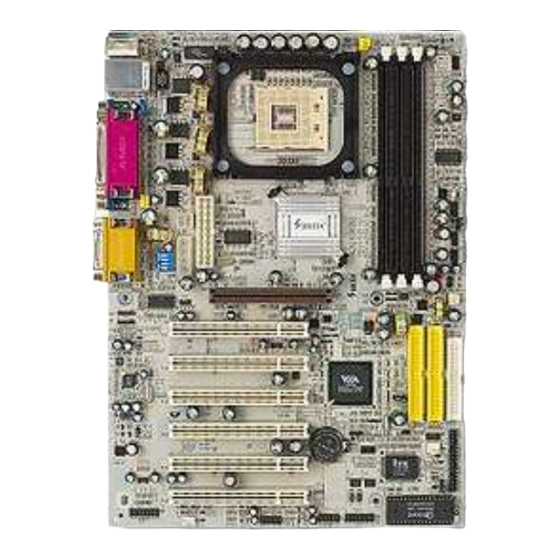
Page 6: 85Drv5 / 85Drv5-L Components And Options
Chapter 1 Specification 1-1 85DRV5 / 85DRV5-L Components and Options PHY LAN Controller for 85DRV5-L only RJ45 PS/2 Mouse (on top) PS/2 K/B (underside) RJ 45 (on top) USB0 (middle) USB1 (underside) Main Power Connector P4x266E Peripheral Power AGP 4X/2X... -
Page 7: Mainboard Specifications
85DRV5 / 85DRV5-L 1-2 Mainboard Specifications 1-2.1 CPU Socket ® CPU Socket 478B on board, supporting Intel Pentium 4 processors in 478-pin package for : -- 533/400MHz System Bus; -- Hyper-pipelined technology; -- Advanced dynamic execution; -- Advanced transfer cache;... -
Page 8: 1-2.6 Advanced System Power Management
Chapter 1 Specification 1-2.6 Advanced System Power Management: • ACPI 1.0 compliant (Advanced Configuration and Power Interface) • APM V1.2 compliant (Legacy Power Management) • ACPI POS (Power On Suspend) • PS/2 Keyboard & Mouse Power On/Wake Up • Supporting Ring Power Up Control for Wake-on-LAN (via Connector WOL1 to add-on PCI LAN card) •... -
Page 9: 1-2.9 Ac'97 Audio Codec On Board
Right, Center and Woofer for complete surrround sound effect • AC’97 Audio Codec Driver enclosed in Support CD for user ’s installation. 1-2.10 LAN on board (85DRV5-L only) Fast Ethernet Controller integrated in VT8235 and PHY VIA VT6103: • Supporting 10/100Mb Fast Ethernet Base-T LAN •... -
Page 10: Mainboard Specification Table
Chapter 1 Specification 1-3 Mainboard Specification Table SL-85DRV5 / 85DRV5-L Specifications and Features Socket 478B for Intel Pentium 4 CPUs North Bridge VIA P4X266E, supporting 533/400MHz FSB South Bridge VIA VT8235 BIOS AMI BIOS Memory Supporting DDR 266/200 SDRM, up to 3GB... -
Page 11: Chipset System Block Diagram
85DRV5 / 85DRV5-L 1-4 Chipset System Block Diagram Intel Pentium 4 478-pin package 533/400 MHz FSB DDR266/200 P4X266E Memory Bus AGP 4X/2X Bus Slot North Bridge SDRAMs 4X (266MB/sec) V-Link (85DRV5-L only) BIOS 10/100 Base T LAN Fast Ethernet Interface... -
Page 12: Chapter 2 Hardware Setup
Chapter 2 Hardware Setup Chapter 2 Hardware Setup To Get Things Ready for Hardware Setup ! 1. We recommend to install your CPU before any other components. For detailed installation instructions of processor, you can also refer to the pamphlet enclosed in your CPU package. 2. -
Page 13: Pentium 4 Cpu And Installation
85DRV5 / 85DRV5-L 2-1 Pentium 4 CPU and Installation 2-1.1 To Identify a Pentium 4 CPU Intel pentium 4 2.4 GHz / 512 / 533 / 1.5V 4) CPU Voltage Vcore 3) System Clock 2) CPU L2 Cache 1) CPU Working Frequency On the heatsink side of a Pentium 4 CPU, there printed is a line of figures to identify its specifications. -
Page 14: 2-1.2 Cpu Installation With Socket 478B
Chapter 2 Hardware Setup 2-1.2 CPU Installation with Socket 478B This series is built with CPU Socket 478B ( 478-pin) supporting the Intel Pentium 4 CPU: • Follow the steps described in this section to install the 478-pin Pen- tium 4 CPU into the on board Socket 478. •... -
Page 15: Pentium 4 Cpu Fan Installation
85DRV5 / 85DRV5-L 2-2 Pentium 4 CPU Fan Installation Pentium 4 Fanbase CPU Fan Connector Press down 4 corners to lock fan to fanbase Connect Fan Connector to CPU FAN connector... -
Page 16: Memory Installation
Chapter 2 Hardware Setup 2-3 Memory Installation How to tackle the memory Modules: • Make sure to unplug your power supply before adding or removing memory module. Failure to do so may cause severe damage to both your mainboard and the memory module. •... -
Page 17: 2-3.2 To Remove A Dimm
85DRV5 / 85DRV5-L 2-3.2 To Remove a DIMM Power off system and press down the holding latches on both sides of slot to release the module from the DIMM slot. PS/2 Mouse (on top) PS/2 K/B (underside) RJ 45 (on top) -
Page 18: Agp 4X/2X Card Installation
Chapter 2 Hardware Setup 2-4 AGP 4X/2X Card Installation The AGP slot on board supports 1.5V AGP4X/2X card only. An AGP 4X card will support a data transfer rate up to 1GB/sec., while an AGP 2X card will do up to 0.5GB/sec only. AGP Accelerator AGP 4X / 2X PS/2 Mouse... -
Page 19: Ide Connector Installation
85DRV5 / 85DRV5-L 2-5 IDE Connector Installation To install IDE Connector, you may connect the blue connector of IDE cable to the primary (IDE1) or secondary(IDE2) connector on board, and then connect the gray connector to your slave device and the black connector to your master device. -
Page 20: Flopy Drive Connector ( Fdc ) Installation
Chapter 2 Hardware Setup 2-6 Flopy Drive Connector ( FDC ) Installation To install FDC (Floppy Drive Connector), you should connect the end of FDC cable with single connector to the board , and connect the other end with two connectors to the floppy drives. PS/2 Mouse (on top) PS/2 K/B... -
Page 21: Atx V 2.03 Power Supply Installation
85DRV5 / 85DRV5-L 2-7 ATX V 2.03 Power Supply Installation +12V Power Connector +12V PWR OK +12V +12V PS/2 Mouse PS ON# (on top) PS/2 K/B (underside) RJ 45 (on top) USB0 (middle) +3.3V -12V USB1 (underside) +3.3V +3.3V Pin1... -
Page 22: Jumper And Switch Settings
Chapter 2 Hardware Setup 2-8 Jumper and Switch Settings The following diagrams show the locations and settings of switch and jumper blocks on the mainboard. Overclock Select Off On On On (Default) CPU clock (MHz) (default) PS/2 Mouse (on top) PS/2 K/B (underside) RJ 45... -
Page 23: 2-8.1 Jbat1: Clear Cmos
85DRV5 / 85DRV5-L How to tackle the Jumpers: A 3-pin Jumper If a pin-header (of 2 or more pins) is designed in such a way that its pins can be closed or linked together to A 2-pin Jumper cap to link set up a specific function, this header two header-pins together. -
Page 24: 2-8.2 Jp1 And Sw1: Cpu Clock/Overclock Select
Chapter 2 Hardware Setup 2-8.2 Jp1 and SW1: CPU Clock/Overclock Select Jp1 and SW1 are designed for CPU clock select and 100MHz CPU overclocking. With Jp1, user can choose the way for a 100MHz CPU to run an overclock on board. SW1 is designed to match and meet the setting of Jp1. -
Page 25: 2-8.3 Jp2: Flash Rom Write Protection
85DRV5 / 85DRV5-L Further Notes on CPU Overclocking: 1. If you have successfully booted system, with or without CPU overclock, you still can try another CPU overclock in BIOS Setup. Please enter BIOS Setup, choose “Frequency/Voltage Control” menu, and take the “Use Linear” option of the “Use CPU Linear Frequency”. -
Page 26: Other Connectors Configuration
Chapter 2 Hardware Setup 2-9 Other Connectors Configuration This section lists out all connectors configurations for users’ reference. 2-9.1 On-board FAN Connectors Void +12V PS/2 Mouse (on top) PS/2 K/B +12V (underside) RJ 45 (on top) SENSOR USB0 (middle) USB1 (underside) Sensor Conn. -
Page 27: 2-9.2 Connector Wol1: Wake On Lan
85DRV5 / 85DRV5-L 2-9.2 Connector WOL1: Wake On LAN 1. This connector connects to a LAN card with a Ring signal output. The connector powers up the system when it receives a wake-up packet or signal through the LAN card. -
Page 28: 2-9.4 Ps/2 Mouse And Ps/2 Keyboard
(underside, purple) 2-9.5 Chassis Panel Connectors H : COM2 Port A : PS/2 Mouse Port : Line Out / B : RJ45 (85DRV5-L only) Front Speaker Out C : LPT1 Port J : Line In / D : Game/MIDI Port... -
Page 29: 2-9.6 Rj45: Lan Connector (85Drv5-L Only)
85DRV5 / 85DRV5-L 2-9.6 RJ45: LAN Connector (85DRV5-L only) One RJ45 connector is on board for network connection. Green LED blinks to indicate Yellow LED “On” to indicate that data transmission is Network hub is in connection undergoing in 10/100 Base T with the system. -
Page 30: 2-9.7 Thermal Sensor Connectors Rt1 And Rt2
Chapter 2 Hardware Setup 2-9.7 Thermal Sensor Connectors RT1 and RT2 PS/2 Mouse (on top) PS/2 K/B (underside) RJ 45 (on top) USB0 (middle) RT1 is mounted with USB1 (underside) Thermal Resistor by default. Main Power Connector P4x266E Peripheral Power AGP 4X/2X Connector VIA VT6103... -
Page 31: 2-9.8 Complex Pin-Header
85DRV5 / 85DRV5-L 2-9.8 Complex Pin-header This complex Pin-header consists of the following connectors for vari- ous supports: PS/2 Mouse (on top) PS/2 K/B (underside) RJ 45 (on top) USB0 (middle) USB1 (underside) Main Power Connector P4x266E Peripheral Power AGP 4X/2X... - Page 32 Chapter 2 Hardware Setup (1) SMI Connector (Optional): Connection: Connected to the case-mounted Suspend Switch. Function: Manually selecting system into the Suspend Mode or “Green Mode” by System mangement interrupt. (2) Power Switch Connector: Connection: Connected to a momentary button or switch. Function: Manually switching the system between “On”...
-
Page 33: 2-9.9 Usb Ports And Usb Pi-Headers
85DRV5 / 85DRV5-L 2-9.9 USB Ports and USB Pi-headers This series provides two USB ports USB0 and USB1 on board sup- porting various USB devices. In addition, pin-headers JUSB1 and JUSB2 are added on board to provide expansion of 4 more optional USB ports by using two additional USB Cables. -
Page 34: 2-9.10 Audio 1: 6-Channel Sound Output Connector (Optional)
Chapter 2 Hardware Setup 2-9.10 Audio 1: 6-channel Sound Output Connector (optional) This series is designed with an optional 6-channel Audio-out connector “Audio1”. If this option is chosen, it will provide 3 additional audio-out ports for the 6-channel sound. 6-channel Audio-out Pin Assignment PS/2 Mouse (on top) PS/2 K/B... -
Page 35: Chapter 3 Software Setup
85DRV5 / 85DRV5-L Chapter 3 Software Setup Drivers, Utilities and Software Installation Support CD: This series will be shipped with a Support CD which contains those necessary driver files, Application Softwares and some helpful utilities. It is a user-friendly, auto-run CD which will open itself up in a CD-ROM automatically. -
Page 36: Open Up Suport Cd
Chapter 3 Software Setup 3-1 Open Up Suport CD 1. Please put the Support CD enclosed in your mainboard package into the CD-ROM drive. In a few seconds, the Main Menu will automatically appear, displaying the contents to be installed for this series: 2. -
Page 37: Proceed To Via 4-In-1 Drivers Installation
85DRV5 / 85DRV5-L 3-2 Proceed to VIA 4-IN-1 Drivers Installation 1. Following the procedures of opening the Support CD, click to “ VIA 4- in-1 Drivers” to proceed. 3. “VIA Service Pack README” 2 . T h e V I A S e r v i c e P a c k... - Page 38 Chapter 3 Software Setup 7. Click on “Click to enable DMA 6 . S e l e c t “ I n s t a l l V I A ATA P I Mode” checkbox to enable V e n d o r S u p p o r t D r i v e r ” DMA function, then click the checkbox, then click the “Next”...
-
Page 39: Ac'97 Audio Driver Installation
85DRV5 / 85DRV5-L 3-3 AC’97 Audio Driver Installation Avance AC97 Audio Codec on board, AC’97 2.2 compatible, supporting: • up to 6 channels of PCM audio output • 6 channel audio consists of Front Left, Front Right, Back Left, Back Right, Center and Woofer for complete surrround sound effect 3-3.1 Driver Installation for 2-channel/6-channel... -
Page 40: 3-3.2 6-Channel Verification
Chapter 3 Software Setup 3-3.2 6-channel V erification After installation of AC’97 6-channel Codec, you must configure the 5.1 Speaker connection to enable the 6-channel audio. 1. Connect your on-board Audio Connector to your 6-channel speakers as depicted in the figure below: Pale Pink Connector to Pale Green Connector Center/Subwoofer Speaker... - Page 41 85DRV5 / 85DRV5-L 3. The AC’97 Audio Configuration” screen will pop out. Clikc the “Speaker Configuration” bar with your mouse. 4. Instantly, the “Speaker Configuration” screen will pop out. Pick the items “6-channel mode for 5.1 speakers output” and “ Synchronize the phonejack switch with the speakers settings”...
- Page 42 Chapter 3 Software Setup 5. At finishing the Speakers Configuration, you can also click the “Speaker Test” bar on the screen to test the 6-channel performance. The figure below is the “Speaker Test” screen with testing instructions enclosed on it. Follow the instructions to perform the Speakers Test.
-
Page 43: Install Usb 2.0 Driver For Win98 / Me / 2000 / Xp
85DRV5 / 85DRV5-L 3-4 Install USB 2.0 Driver for Win98 / Me / 2000 / XP VIA USB V2,0is already integrated on board. Its 480Mb/s transfer rate supports operating system Win98/Me/2000/XP. USB Driver installa- tion procedures are of similar steps in these systems. Please take the following illustrations from Win XP as the USB driver installation guide: 1. - Page 44 Chapter 3 Software Setup 3. Instantly, next screen will pop up to prompt you to select component. Select “Install USB Driver” and click “Next” button to continue. Next 4. The USB 2.0 Setup Program will then guide you through the whole driver setup until the “Finish”...
-
Page 45: Install Hardware Monitor Utility
85DRV5 / 85DRV5-L 3-5 Install Hardware Monitor Utility 3-5.1 Installation Hardware Monitor is built in chip IT8705F of this series. Its in- stallation is programed to a fully automated mode on Windows 9X/ Me/NT4/2000/XP. User can follow the model installation below for its installation on various Windows System. - Page 46 Chapter 3 Software Setup 3-5.2 V erification 1. After restarting your computer, click “Start” and choose the path \ P r o g r a m s \ I T E S m a r t Accessories\ITE Smart Guardian to open the main window of the Hardware Doctor.
- Page 47 85DRV5 / 85DRV5-L 3-6 Install VIA LAN Drivers (for 85DRV5-L only) 3-6-1. VIA6183 LAN driver on Windows 9X The LAN driver contained in the Support CD is not included in the Autorun Menu. To install VIA LAN driver on Windows 9X, please follow the steps shown below: 1.
- Page 48 Chapter 3 Software Setup 5. In the “Update device Driver Wizard” screen, click “Next” to continue until you see a dialog box asking you to “Specify a location” for the driver. You should now insert the Support CD into your CD-ROM. 6.
- Page 49 85DRV5 / 85DRV5-L 3-6-2. VIA6183 LAN driver on Windows NT4.0 1. When you newly install Win NT4, the Setup program will ask you whether your computer will participate on a network. please check “Do not connect this computer to a network at this time” and continue with your installation.
- Page 50 Chapter 3 Software Setup 10. To verify that the onboard VIA LAN Controller has been set up in system, please click “Start”, then “Control Panel”, then “Network”. 11. In the “Network” screen, click the “Adapter” bar. You can now see the “VIA PCI 10/100Mb Fast Ethernet Adapter is already installed in system.
Need help?
Do you have a question about the 85DRV5 and is the answer not in the manual?
Questions and answers