
Related Manuals for RGBlink IC2+


Summary of Contents for RGBlink IC2+
- Page 1 IC2+ AV over IP Encoder & KVW/Scaling Decoder User Manual Article NO: RGB-RD-UM-IC2+ E000 Version NO: V1.0...
- Page 2 Before using this product, please read this manual carefully and keep it for reference. Read the safety operation guide carefully.Pay attention to reminder symbol: This manual is only for user operation instructions, not for maintenance services. The dangerous and Attention. expiration date of the function is March 20, 2020.
- Page 3 Safety Operation Guide To ensure reliable use of the equipment and personnel safety, observe the following precautions when installing, using, and maintaining the equipment: Danger There are live parts in the equipment, non-professionals without permission, please do not disassemble the equipment, so as to avoid the risk of electric shock.
-
Page 4: Table Of Contents
Contents Chapter 1 The Introduction .................1 1.1 Introduction ....................1 1.2 Functional Features ..................1 1.3 Components of Packaging ................2 Chapter 2 Product Appearance ................3 2.1 Front Panel ....................3 2.2 Rear Panel ......................3 Chapter 3 System Connection ................6 3.1 Matters Needing Attention ................6 3.2 Connection Configuration Diagram ...............7 Chapter 4 System Settings .................. - Page 5 5.9 Configure Upload and Download ..............37 5.10 Configuration Saving, Backing up and Importing ........38 Chapter 6 Perform Operations on the Client .............40 Chapter 7 KVM operation ................. 43 Chapter 8 Upgrade the Firmware ..............44 8.1 Matters Needing Attention ................ 44 8.2 Check and Upgrade the Mainboard ............
-
Page 6: Chapter 1 The Introduction
Chapter 1 The Introduction 1.1 Introduction This is a device that makes full use of advanced technologies such as video compression processing, network technology, visualization technology, and centralized control. It integrates multiple functions, including video stitching and processing, KVM cooperative management, audio processing, centralized control, and photoelectric mutual backup, and integrates codec with IP network. -
Page 7: Components Of Packaging
Optional OPto-electronic mutual backup is supported. The front panel supports IP display. 1.3 Components of Packaging The host x1 Hanging ear x2 Screw (securing mounting ears) X4 Machine foot x4 The instructions X1 Certificate of Quality & Warranty cardX1 Phoenix seat X4 Note: The machine is strictly packed before leaving the factory. -
Page 8: Chapter 2 Product Appearance
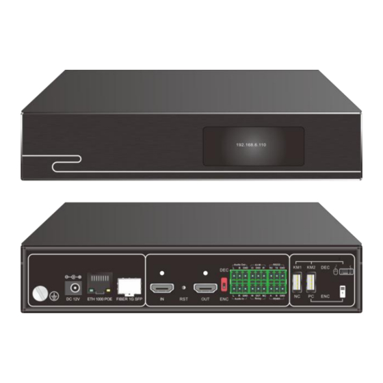
Chapter 2 Product Appearance 2.1 Front Panel Figure 2-1 Front panel of the switch Name Description OLED screen 0.91 inch OLED screen, supporting IP address, CPU usage, temperature, startup time, network display, etc. 2.2 Rear Panel Figure 2-2 Rear panel of the switch... - Page 9 Grounding Name Description screw For ground wire DC 12V power 12V2A female connector of the DC power supply port connects to the male connector of the 5.5 x 2.1 DC power supply and interconnects with the network POE power supply。 ETH 1000 POE Gigabit network ports that support POE power ...
- Page 10 Name Description IR/IO IR/IO multiplexing 3pin interface, IR and IO function of two options. The IR can only receive or send. IO Supports receiving or sending. There are two ways of IO. Relay Relay interface, 12V Max. IN indicates a 12V input ...
-
Page 11: Chapter 3 System Connection
Chapter 3 System Connection 3.1 Matters Needing Attention The system installation and use environment should be kept clean, with proper temperature and humidity, and good ventilation; All power switches, plugs, sockets, and power cables in the system must be insulated safely. Connect peripheral devices and power on the system. -
Page 12: Connection Configuration Diagram
3.2 Connection Configuration Diagram Figure 3-1 Connection configuration diagram... -
Page 13: Chapter 4 System Settings
Chapter 4 System Settings The node has network ports. The default IP address of the node is 192.168.*.*, mask 255.255.0.0, and gateway 192.168.*.1 (The IP address and gateway can be changed) Nodes and control computers are connected to the LAN as shown below. Three major pieces of software are required for onsite distributed commissioning, as shown below. -
Page 14: Parameter Settings
4.1 Parameter Settings 4.1.1 UMPlatform Interface is Introduced Current UMPlatform software version Node type options: The software distinguishes input, output and parameter modification of other nodes Scan:Click and broadcast to query data. Nodes that receive broadcast information will return node information. Restart:Restart the selected device. -
Page 15: Set The Node Name And Ip Address
Advanced options:Mainly set some very useful and advanced parameters, password = (current year + month + day) X current time, such as 15:31 on March 1, 2022. Password = (2022+3+1) x15=30375 (10) Node handsome selection function: This function is used to select nodes of different device models for upgrade. - Page 16 Step 3: Change the node name and IP address as planned. Step 4: If some nodes are not detected, perform the following steps to scan across network segments. Step 5: According to the scanned network segment, set the IP of the computer again to the same network segment as the node, that is, repeat step 1 to Step 4, until the IP of all nodes is modified correctly.
-
Page 17: Set General Node Parameters
Step 6: Do the same for the output node. Step 7:Some parameters are advanced parameters. You need to enter a password to set them. As shown in the figure below. Enter password = sum of current year, month and day X current time, such as 9 o 'clock on March 5, 2022, then calculate (2022+3+5) X 9=18270, enter password 18270, you can enter the parameter setting of advanced options. - Page 18 Step 2: Set the audio input mode Check node parameters and audio input mode. Set the HDMI input or 3.5mm (3pin Phoenix terminal) input according to the actual situation. Other parameters do not need to be modified. HDMI input Settings are shown in the following figure. Do not modify other parameters.
- Page 19 3.5mm (3pin phoenix terminal) input Settings are shown in the following figure. Do not modify other parameters.
-
Page 20: Input Node 4K Input Parameter Settings
4.1.4 Input Node 4K Input Parameter Settings Input node 4K Input parameter Settings Enter node-Advanced Settings -system-EDID-4K. The setting takes effect after a restart. Input node-code setting to view the resolution of the current HDMI interface input status, as shown in the following figure. 4.1.5 KVM Input Node Settings This step is based on 4.1.2. -
Page 21: General Parameter Settings For The Output Node
Set access parameters for the extended screen and KVM of a non-Windows Enter node - Advanced Settings - System - Coordinate selection -rel and restart. (REL- operating system relative mode, ABS -absolute mode) 4.1.6 General Parameter Settings for the Output Node This step is performed on the basis of 4.1.2. - Page 22 The HDMI output Settings are shown below, and the volume is adjusted to the maximum (0). You do not need to modify other parameters. Step 2: Set the protocol version Check and set Advanced Settings - Functionality (protocol version) for SCODE.
-
Page 23: Set Parameters Of The Output Node Of The Splice Wall
4.1.7 Set Parameters of the Output Node of the Splice Wall On the basis of 4.1.4 You can set the output resolution based on the display. The default output resolution is 1080P@60Hz. Support 3840x2160@30, 1080P@60, 1080P@30, 720P@6 and custom. Other parameters do not need to be modified ... - Page 24 (6) Network 4K decoding, HDMI 2K output. For parameter Settings, see the following figure (default Settings). See Chapter 5 for the video wall binding node. (7) Network 4K decoding, HDMI 4K output. For parameter Settings, see the following figure (default Settings). See Chapter 5 for the video wall binding node.
-
Page 25: Configure The Kvm Output Node
4.1.8 Configure the KVM Output Node Proceed on the basis of 4.1.4 Enable the KVM function. See Chapter 5 for more details on the seat binding node. Step 1: Advanced Settings - Functions - Enable Settings for the KVM module.。 ... -
Page 26: Rs232 Configure Transparent Serial Port Transmission
4.1.9 RS232 Configure Transparent Serial Port Transmission Function: Connects to a third-party device through an RS232 interface Regardless of audio and video, specify the device IP address and port and network transparent transmission command The RS232 serial port supports baud rates of 4800, 9600, 15200, 38400 and 115200. -
Page 27: Rs485 Configure Transparent Serial Port Transmission
Step 4: The RS232 device sends the serial port instruction, and the node receives the serial port instruction and forwards it to the network device through the network. The parameter Settings are as follows. For example, IP address and port number of the network device 192.168.0.222:16232。... -
Page 28: Relay Configuration
Step 4: The network sends instructions to the RS485 device through the node. After receiving the serial port instructions, the node sends them to the RS485 device through the serial port. 4.1.11 Relay Configuration Function: 12V circuit switch. Regardless of audio and video, the relay switch IN the network transmission ... -
Page 29: Chapter 5 System Design And Configuration
Chapter 5 System Design and Configuration 5.1 Overview The designer software is applied to node input configuration, output splicing wall configuration, seat configuration and user authorization configuration. Before using the UMPlatform, configure the node network and output resolution based on the network plan. After the configuration, ensure that each node has been bound. 5.2 Log in to Software Double-click on the following icon ,Click the IP address... -
Page 30: Signal Source Configuration
5.3 Signal Source Configuration 5.3.1 Clear the Configuration of the Current Signal Source Input-seting,clear then New. 5.3.2 Add Signal Group 5.3.3 Del Signal Group... - Page 31 5.3.4 Renames Signal Group Double-click the name to enter the modify mode. 5.3.5 The Group Binds the Input Node Bind all input sources. Bindable partial input source.
-
Page 32: Video Wall Configuration
5.3.6 Associative Setting of Interface Signals and Input Groups UI design-PageList-Panel1; Choose Signal module; Click Link to select the established signal group. Multiple selection is supported. 5.4 Video Wall Configuration 5.4.1 Set the Panel Scale Double click video wall... - Page 33 Enter the Panel Setting: Rows<=12,Columes<=20 In this example, it is set to 1,1. 5.4.2 Bind Output Nodes Select a node in the output list and click on the middle Panel square area. Realize the binding of the output node and the video wall position.
- Page 34 5.4.3 Set the Wall Resolution for Each Node The pixels in each row and column are the same, which is consistent with the actual node resolution. 5.4.4 The Wall Audio Output Node Setting The audio follow settings page is displayed.
- Page 35 Set the audio output area. You can configure the nXm by region. In this example, it is set to 1X1. Bind the audio output node. Select the middle area (bright blue) and double-click the output node in the output list to bind the IP address of the corresponding output node in the associated node.
- Page 36 5.4.6 Volume Slider Binding UI design-PageList-Panel 1. Select the bar chart in the middle of the slider module.Link- Double-click the output list input source, click on the right side of the command... To view the bound IP address. 5.4.7 Volume Read Back Binding UI design-PageList-Panel1.Select the middle bar chart of the get back module.
-
Page 37: Kvm Seting
5.5 KVM Seting Refer to the following figure to select different display sizes for seats. A single seat can support a maximum of 2X4 splice screen size. Double-click to change the seat name. Click - Delete the selected seat. Select a seat, and then select an unallocated output node in the output list, and then click one of the boxes above the middle area of the software to realize the binding between the output node and the seat node. -
Page 38: Authorization
5.6 Authorization The default user name is admin and the password is Admin123. The account cannot be changed, and the password can be changed. A strong 8-digit password containing upper and lower case digits is mandatory. Must not contain special symbols. The default account has all permissions and cannot be changed. -
Page 39: Ui Design - Button Configuration
The user is authorized by the client. If this item is selected, the user has the operation rights on the page. User KVM agent authorization includes agent login, agent push, signal source grouping, video wall, standard functions, and account sharing login multiple agent functions. If you select this option, you have this permission. - Page 40 5.7.1 Page Adjustment Button Settings Click the button and select the corresponding page on the right of the page button in Configuration - Basic Properties. 5.7.2 Button to Send UDP Command Settings To select the page where you can add or modify commands based on existing buttons, click on the right side of Configuration-Command...
- Page 41 5.7.3 Button to Send TCP Command Settings 5.7.4 Mutually Exclusive Button Settings If multiple buttons are mutually exclusive, select the group button and set the same group number. The two buttons in the picture below.The group ID cannot exceed 99. Button mode selection toggle.
-
Page 42: Practice Test
5.8 Practice Test Click the button below to perform the simulation test. 5.9 Configure Upload and Download 5.9.1 Configure Upload After the configuration is complete, you need to upload it to each node for the configuration to take effect. If the output node is configured in KVM mode for the first time, you need to completely power off. -
Page 43: Configuration Saving, Backing Up And Importing
5.10 Configuration Saving, Backing up and Importing 5.10.1 Save the Configuration 5.10.2 Configure Backup Contains the current configuration and data file saved. - Page 44 5.10.3 Import the Configuration To import the configuration, you need to save the data file in the original backup file to the designer directory. Then open the TXT document through the designer.The configuration is overwritten after the import. Exercise caution when performing this operation.
-
Page 45: Chapter 6 Perform Operations On The Client
Chapter 6 Perform Operations on the Client Running the Client. Enter the local network IP address The default password is admin or Admin123... - Page 46 After login, you can pull the signal to the wall, click the button to realize the page jump, etc. As shown in the figure below. If no preview is found, you can disable other networks, including wireless networks, only the network connected to the distributed network, and then open the client to achieve preview.
- Page 47 Name Description Click Take Effect to make the preset arrangement The default window of the client, and the real-time window configuration opening of other clients of the current video wall will not be updated at this time. The operation on the local client is temporarily performed on the client.
-
Page 48: Chapter 7 Kvm Operation
Chapter 7 KVM operation K for keyboard, V for display wall, M for mouse. In the seat area, KVM is used to remotely control the host. Through the distributed node, the mouse and keyboard signals are encoded into IP packets, which are transmitted by the switch to the input node, and then unscrambled into USB signals. -
Page 49: Chapter 8 Upgrade The Firmware
Chapter 8 Upgrade the firmware 8.1 Matters Needing Attention Before the upgrade, check the mainboard information of the device before uploading the upgrade file. Do not change the name of the upgrade file. If not, contact support engineers for confirmation. 8.2 Check and Upgrade the Mainboard Step 1: Open... -
Page 50: Chapter 9 Size
Chapter 9 Size... -
Page 51: Chapter 10 Installation
Chapter 10 Installation 10.1 Hanging Installation 10.2 Rack Installation 6U height, standard 19-inch rack mount, rack size W483 X H265, as shown below. -
Page 52: Chapter 11 After Sales Service
Chapter 11 After Sales Service If you use this product, in the warranty period, the normal use of the product, due to its own quality problems caused by the failure, the company will be responsible for free repair. The company provides two-year warranty service for this product, the warranty period start date:... -
Page 53: Chapter 12 Appendix
Chapter 12 Appendix 12.1 Terms & Definitions ●RCA: Connector used primarily in consumer AV equipment for both audio and video. The RCA connector was developed by the Radio Corporation of America. ●BNC: Stands for Bayonet Neill-Concelman. A cable connector used extensively in television (named for its inventors). - Page 54 ●6G-SDI: Standardized in SMPTE ST-2081 released in 2015, 6Gbit/s bitrate and able to support 2160p@30. ●12G-SDI: Standardized in SMPTE ST-2082 released in 2015, 12Gbit/s bitrate and able to support 2160p@60. ●U-SDI: Technology for transmitting large-volume 8K signals over a single cable. a signal interface called the ultra high definition signal/data interface (U-SDI) for transmitting 4K and 8K signals using a single optical cable.
- Page 55 ●DP 1.1: Was ratified on 2 April 2007, and version 1.1a was ratified on 11 January 2008. DisplayPort 1.1 allow a maximum bandwidth of 10.8 Gbit/s (8.64 Gbit/s data rate) over a standard 4-lane main link, enough to support 1920x1080@60Hz ●DP 1.2: Introduced on 7 January 2010, effective bandwidth to 17.28 Gbit/s support increased resolutions, higher refresh rates, and greater color depth, maximum resolution 3840 × 2160@60Hz...
- Page 56 ●LC:(Lucent Connector) is a small factor connector (uses only a 1.25mm ferrule diameter) that has a snap coupling mechanism. Because of its small dimensions, it is the perfect fit for high-density connections, XFP, SFP, and SFP+ transceivers. ●FC: (Ferrule Connector) is a screw type connector with a 2.5mm ferrule. FC is a round shaped threaded fiber optic connector,mostly used on Datacom, telecom, measurement equipment, single-mode laser.
- Page 57 ●SMPTE: Society of Motion image and Television Engineers. A global organization, based in the United States, that sets standards for baseband visual communications. This includes film as well as video and television standards. ●VESA: Video Electronics Standards Association. An organization facilitating computer graphics through standards.
- Page 58 media servers. The protocol is used for establishing and controlling media sessions between end points. ●MPEG: Moving Picture Experts Group is a working group formed from ISO and IEC developing standards that allow audio/video digital compression and Transmission. ●H.264: Also known as AVC (Advanced Video Coding) or MPEG-4i is a common video compression standard.
- Page 59 ●Brightness: Usually refers to the amount or intensity of video light produced on a screen without regard to colour. Sometimes called black level. ●Contrast Ratio: The ratio of the high light output level divided by the low light output level. In theory, the contrast ratio of the television system should be at least 100:1, if not 300:1.
- Page 60 ●Seamless Switching: A feature found on many video switchers. This feature causes the switcher to wait until the vertical interval to switch. This avoids a glitch (temporary scrambling) which often is seen when switching between sources. ●Scaling: A conversion of a video or computer graphic signal from a starting resolution to a new resolution.
-
Page 61: Revision History
0000# Release Aster All information herein is Xiamen RGBlink Science & Technology Co Ltd. excepting note is a registered trademark of Xiamen RGBlink Science & Technology Co Ltd. While all efforts are made for accuracy at time of printing, we reserve the right to alter... -
Page 62: Support
12.3 Support...
Need help?
Do you have a question about the IC2+ and is the answer not in the manual?
Questions and answers