Table of Contents
Advertisement
Quick Links
Advertisement
Table of Contents

Related Manuals for RGBlink IC2


Summary of Contents for RGBlink IC2
- Page 1 User Manual Article NO: RGB-RD-UM-IC2 E000 Version NO: V1.0...
-
Page 2: Table Of Contents
Content Declarations................................... 3 FCC/Warranty.................................3 Operators Safety Summary............................4 Installation Safety Summary..........................4 Chapter 1 Your Product ..............................6 1.1 In the Box................................. 6 1.2 Product Overview............................7 1.2.1 Front Panel............................8 1.2.2 Rear Panel............................. 9 1.2.3 Dimension............................10 Chapter 2 Install Your Product............................. 11 2.1 Plug in Power.............................. -
Page 3: Declarations
RGBlink. If the purchaser or a third party carries out modifications or repairs on goods delivered by RGBlink, or if the goods are handled incorrectly, in particular if the systems are commissioned operated incorrectly or if, after the transfer of risks, the goods are subject to influences not agreed upon in the contract, all guarantee claims of the purchaser will be rendered invalid. -
Page 4: Operators Safety Summary
Operators Safety Summary The general safety information in this summary is for operating personnel. Do Not Remove Covers or Panels There are no user-serviceable parts within the unit. Removal of the top cover will expose dangerous voltages. To avoid personal injury, do not remove the top cover. Do not operate the unit without the cover installed. - Page 5 Unpacking and Inspection Before opening product shipping box, inspect it for damage. If you find any damage, notify the shipping carrier immediately for all claims adjustments. As you open the box, compare its contents against the packing slip. If you find any shortages, contact your sales representative. Once you have removed all the components from their packaging and checked that all the listed components are present, visually inspect the system to ensure there was no damage during shipping.
-
Page 6: Chapter 1 Your Product
Chapter 1 Your Product 1.1 In the Box USB Cable Certification Power Adapter Note: Power Adapter is supplied according to destination market. User Manual... -
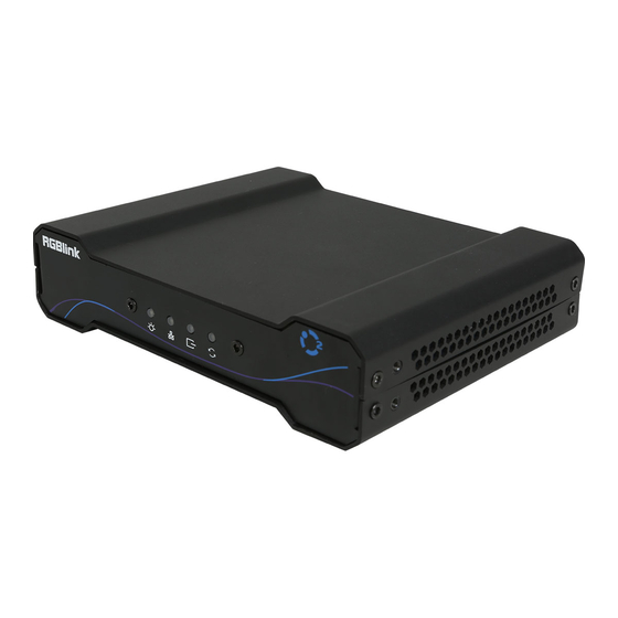
Page 7: Product Overview
Meeting the growing requirements for distributed management, control and display of compute and other video systems, IC2 is so much more than KVM.IC2 provides secure IP based and advanced RGBlink video technologies for demanding environments where high performance and quality are essential. -
Page 8: Front Panel
1.2.1 Front Panel Item Description Power light Power on Connection light Successful network connection Signal light Successful signal connection Abnormal light Device hardware runs abnormally User Manual... -
Page 9: Rear Panel
1.2.2 Rear Panel Connectors Description Power Connect to 12V power supply 1×RJ45,connect to Gigabit Switch; Support PoE power supply HDMI IN 1×HDMI-A As RX.it is useless; As TX,connect to media player or camera. Switch Switch between Receiver(RX) and Transmitter(TX) HDMI OUT 1×HDMI-A As RX,connect to display;... -
Page 10: Dimension
1.2.3 Dimension Following is the dimension of IC2 for your reference: Dimension of IC2 :160mm×128mm×37.1mm User Manual... -
Page 11: Chapter 2 Install Your Product
5. Connect control computer to Gigabit Switch via CAT6 cable. Note:Only the USB port with the host icon can achieve KVM control;The Gigabit Switch is essential and make sure that all the IC2 and control computer shall in the same network segment. User Manual... -
Page 12: Rack Installation
2.3 Rack Installation Diagrams of Rack Installation are as follow: Front View Rear View User Manual... -
Page 13: Chapter 3 Use Your Product
Chapter 3 Use Your Product 3.1 Software Installation Environment Requirements: Window Processor: 1 GHz or above 32 bit or 64 bit processor Memory: 4 GB or more Graphics: Support Direct X9 128M or above (open AERO effect) Hard disk space: Above 16G (primary partitions, NTFS format) Monitor:... - Page 14 1. Double click this icon ,and enter the log on 2. Click Activate and scan the QR code an email from RGBlink Registrations will be sent interface as follow to the Register email address. Click Register and fill in the blank with first name, last name, email, company and country and then click Register Now.
-
Page 15: Software Operation
4. Keep the user name as “Admin” and 3. Type in the activate code and confirm. password blank and then click Start Now. 3.2 Software Operation 3.2.1 Search Device to enter System Settings interface,and select “IC” in the list of Find Device. 1. - Page 16 3.2.2 Input Port 1. Property Click input port to check property,including IP,Name,Main Stream,Sub Stream and Preview Stream 2. Network Edit IP Address,Netmask and Gateway for input port. 3. Venc Edit Main Stream,Sub1 Stream,Sub2 Stream and other parameters. User Manual...
- Page 17 Venc Style: The higher the resolutions,the higher the frame rate,the clearer the video is.The Venc Style should not exceed the input resolution,and they will be the same by default. Venc Type: H.264/H.265,H.264 by default Frame:The high the frame rate,the smoother the video,A default frame rate of 60 can significantly improve the sense of interaction and realism.The frame rate is up to 60.
- Page 18 Out Same In/Hardware Loop:ON/OFF Brightness/Contract/Hue/Saturation:50 as default Snap Set snap parameters Crop Vi Crop:ON/OFF Crop X/Y: the starting crop horizontal and vertical position Crop Width:256<Crop Width<Width Total-Crop X; Crop Height:128<Crop Height<Height Total-Crop Height; Venc Style≤Crop Resolutions≤Input Resolutions User Manual...
- Page 19 OSD:ON/OFF OSD Content:The content is limited in length,usually no more than 20 words. Front Size/Color/OSD X/Y:adjustable as shown in the picture SysInfo You can check the Product Name/MainBoard/System/Switch to Output 3.2.3 Output Port 1. Network Edit IP Address,Netmask and Gateway for output port. User Manual...
- Page 20 2. Audio Sample Rate: refers to the sampling numbers to audio in 1 second.The higher the sampling frequency, the more real and natural the sound will be restored. The product supports 48000. In Mode:HDMI/3.5MM; Out Mode:HDMI/3.5MM; Volume: -10 as default Auto Adjust/Audio Vo : ON/OFF 3.
- Page 21 Vdec Max Resolution:support up to 1920*1080; Vdec Num:The number of decoding channels is related to the maximum decoding resolution. When the maximum decoding resolution is 1080p, the corresponding number of decoding channels is 16; Vdec Mode: stream/frame,stream as default; Output Resolution:up to 1920*1080; Output Mode:HDMI/DVI/AUTO,HDMI as default;...
- Page 22 Enable:ON/OFF Set the snap and crop parameters Shortcut Key KVM/Title/LOGO/VO/:ON/OFF Fix MAC:OFF as default Background BG Mode:pure/image SysInfo Check Product Name,MainBoard,System,Switch to Output 3.2.4 Input Manage Click the icon to enter <Input Manage> interface,as shown in the figure below,there is a list of <Input Node>...
- Page 23 Signal Group 1. In the <Signal Group>menu,click “+” to add a new signal group,click to edit the group name,click to delete a signal group. 2. Group Choose:there are 6 kinds of Groups to be selected.You can select different Groups in one Signal Group.
- Page 24 4. Select Input Nodes and Groups, which have been set in last step, for different Signal Groups. 3.2.5 Output Manage Click the icon to enter <Output Manage> interface,as shown in the figure below:there is a list of <Output Node> in the left side and <Videowall> and <KVM> in the right side: User Manual...
- Page 25 Videowall 1. In the <Videowall> menu,click “+” to add a new Video Wall,click to edit videowall name,and click to delete videowall. 2. In the<Row/Col Set> menu,fill in the number of row and col you want.For example,set row as 2,col as 2,there will be a 2*2 videowall show in the interface. 3.
- Page 26 2. There are 8 kinds of KVM Sets to be selected as shown in the figure: 3. Drag and drop the output nodes in the left side to the KVM as shown in the figure below,please note that the same output node cannot exist in both videowall and KVM at the same time. 3.2.6 User Manage Click the icon to enter<User Manage>interface as shown in the figure:...
- Page 27 1. In the<Customize>menu,edit User Name,Password and User Level; In the <User List>menu,click “+” to add a new user. 2. Authorization Setting Admin enjoys all the permissions of Signal Group,Video Wall and KVM. Other users can be assign permissions according to their needs Video Wall:Scene,Full Screen,Dock,Free,Clear.
- Page 28 3.2.7 Videowall Manage Click the icon to enter<Videowall Manage>interface as shown in the figure below,there is a list of <Signal Group> in the left side,<Videowall> and <Scene List> in the right side. 1. In the <Video Wall>menu,click the Video Wall you want to set. User Manual...
- Page 29 2. Each videowall can support 16 scenes. User Manual...
-
Page 30: Computer Operation
3.3 Computer Operation IC2 supports keyboard and mouse operation for mode conversion: 1. Press “Ctrl”/“Alt”/“Shift” three times to enter Login Mode. 2. Fill in the name and password: ● Press “Ctrl” three times to enter Local Manage Mode. ● Press “Alt” three times to enter Videowall Manage Mode. -
Page 31: Local Manage Mode
② Press “Enter” to confirm(Incorrect user name or password will be indicated in red) ③ The background image can be configured with designer,and can be selected in either all-screen mode or single-screen mode. 3.3.2 Local Manage Mode 1. No signal ①... - Page 32 ① If there is signal and users enjoy Mark permission,then you can mark on the screen. 3.Marking ① Select the size and color ② Lock the permission ● Locked: Only users with high permissions can mark ● unlocked: All users with mark permission can operate ③...
-
Page 33: Videowall Manage Mode
3.3.3 Videowall Manage Mode 1. Scene menu closed ① Single click mouse to select videowall ② Single click mouse to select signal group ③ Single click mouse to select signal page(8/page) ④ Drag and drop to switch signals(you can also drag signals to other screen) ⑤... -
Page 34: Kvm Mode
2. Scene Menu Opened ① Page turning/edit name/save/clear ● Choose one scene first and then edit ● Name can only be filled in lowercase English ● Clear saved scene ② Single click to chosen scene(KVM will preview chosen scene,but real-time videowall will not change) ③... -
Page 35: Normal Usage Mode
① Single click to select the KVM page(4/page) ② Single click to select Signal Group ③ Single click to select Signal Source page(8/page) ④ Drag and drop signal sources to KVM(push at most 4 signals to one KVM) ⑤ Select the permission for KVM ⑥... - Page 36 2. Be Pushing(with signals) ① Pushing List(6 at most, can be from different users) ② Drag and drop signal sources to receive and push(users can also drag and drop signals to other screen) ③ Single click to delete pushing(Users can only delete the pushing from low-permission users) 2.
-
Page 37: Chapter 4 Ordering Codes
Chapter 4 Ordering Codes 4.1 Product Code 660-0002-01-0 User Manual... -
Page 38: Chapter 5 Appendix
Chapter 5 Appendix 5.1 Specification Connectors Input HDMI 1×HDMI-A Output HDMI 1×HDMI-A Communication 2×USB-A 1×RJ45 RS232 1×Phoenix Audio Audio In 1×3 pin Phoenix Audio Out 1×3 pin Phoenix Power 1×DC Jack Performance Input Resolutions HDMI SMPTE 720p@60 VESA 1024×768@60 | 1280×1024@60 | 1440×900@60 | 1920×1080@60 Output Resolutions HDMI SMPTE... - Page 39 professional applications the connector is BNC type. ●YPbPr: Used to describe the colour space for progressive-scan. Otherwise known as component video. ●VGA: Video Graphics Array. VGA is an analog signal typically used on earlier computers. The signal is non-interlaced in modes 1, 2, and 3 and interlaced when using in mode.
- Page 40 ●HDMI 2.0b: Was released March, 2016, support for HDR Video transport and extends the static metadata signaling to include Hybrid Log-Gamma (HLG). ●HDMI 2.1: Released on November 28, 2017. It adds support for higher resolutions and higher refresh rates, Dynamic HDR including 4K 120 Hz and 120 Hz.
- Page 41 ●FC: (Ferrule Connector) is a screw type connector with a 2.5mm ferrule. FC is a round shaped threaded fiber optic connector,mostly used on Datacom, telecom, measurement equipment, single-mode laser. ●ST: (Straight Tip) was invented by AT&T and uses a bayonet mount along with a long spring-loaded ferrule to support the fiber.
- Page 42 ●SMPTE: Society of Motion image and Television Engineers. A global organization, based in the United States, that sets standards for baseband visual communications. This includes film as well as video and television standards. ●VESA: Video Electronics Standards Association. An organization facilitating computer graphics through standards. ●HDCP: High-bandwidth Digital Content Protection (HDCP) was developed by Intel Corporation an is in wide use for protection of video during transmission between devices.
- Page 43 ●H.265: Also known as HEVC (High Efficiency Video Coding )H.265 is the successor to the widely used H.264/AVC digital video coding standard. Developed under the auspices of ITU, resolutions up to 8192x4320 may be compressed. ●API: An Application Programming Interface (API) provides a predefined function which allows access capabilities andfeatures orroutines viaa software or hardware, without accessing source code or understanding the details of inner working mechanism.
- Page 44 ●Genlock: Allows synchronisation of otherwise video devices. A signal generator provides a signal pulses which connected devices can reference. Also see Black Burst and Color Burst. ●Blackburst: The video waveform without the video elements.It includes the vertical sync, horizontal sync, and the Chroma burst information.
-
Page 45: Revision History
Release Sylvia All information herein is Xiamen RGBlink Science & Technology Co Ltd. excepting noted. is a registered trademark of Xiamen RGBlink Science & Technology Co Ltd. While all efforts are made for accuracy at time of printing, we reserve the right to alter otherwise make change without notice. -
Page 46: Chapter 6 Support
Chapter 6 Support 6.1 Contact Us User Manual...
Need help?
Do you have a question about the IC2 and is the answer not in the manual?
Questions and answers