Table of Contents
Advertisement
Quick Links
Advertisement
Table of Contents

Related Manuals for RGBlink MSP 200PRO


Summary of Contents for RGBlink MSP 200PRO
- Page 1 MSP 200PRO USER MANUAL Article No: RGB-RD-UM-200PRO E001 Revision No: V1.0...
-
Page 2: Table Of Contents
5.1 Contact Us ............................. 21 Chapter 6 Appendix ............................. 22 6.1 Specification ..........................22 6.2 Software Upgrade .......................... 24 6.3 Installing the Battery ........................27 6.4 Terms & Definitions ........................30 6.5 Revision History ..........................34 MSP 200PRO User Manual... -
Page 3: Declarations
RGBlink. If the purchaser or a third party carries out modifications or repairs on goods delivered by RGBlink, or if the goods are handled incorrectly, in particular if the systems are commissioned operated incorrectly or if, after the transfer of risks, the goods are subject to influences not agreed upon in the contract, all guarantee claims of the purchaser will be rendered invalid. -
Page 4: Operators Safety Summary
Installation Safety Summary Safety Precautions For all MSP 200PRO processor installation procedures, please observe the following important safety and handling rules to avoid damage to yourself and the equipment. To protect users from electric shock, ensure that the chassis connects to earth via the ground wire provided in the AC power Cord. -
Page 5: Site Preparation
Site Preparation The environment in which you install your MSP 200PRO should be clean, properly lit, free from static, and have adequate power, ventilation, and space for all components. -
Page 6: Chapter 1 Your Product
Chapter 1 Your Product 1.1 In the Box AC Power Cord Flight Case Lithium Ion Warranty Card & Battery USB Files QC Declaration Screw Driver Note: The lithium ion battery is optional. MSP 200PRO User Manual... -
Page 7: Product Overview
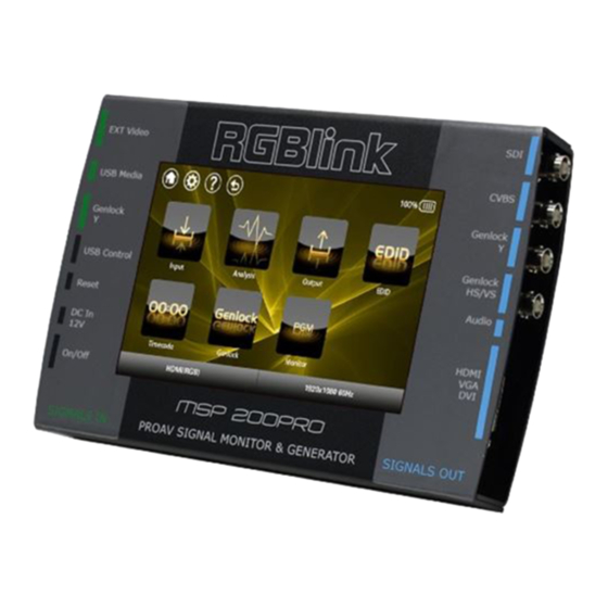
Chapter 1: Your Product 1.2 Product Overview Format and Test Pattern Generation are just two of the many features of MSP 200PRO. MSP 200PRO allows on board preview of an HDMI (or optionally SDI) source along with format inspection. There is wave form monitoring and video monitoring capabilities too. Popular test patterns can be easy selected with motion or without, and time code can be generated and displayed allowing inspection frame delay. -
Page 8: Interface Instruction
DVI +VGA, VGA output connector can be connected to monitor or projector which has VGA interface. HDMI connector (via DVI to HDMI cable), connect to the display device, video processor or matrix with HDMI input. MSP 200PRO User Manual... -
Page 9: Power Connection
For product upgrades or copying the audio files. Reset Push Reset button to modify the settings if the touch screen works improperly due to incorrect screen calibration. Power Connection Power Input Standard 12V/3A power supply. Power Switch Illuminated power switch. MSP 200PRO User Manual... -
Page 10: Dimension
Chapter 1: Your Product 1.2.2 Dimension Following is the dimension of MSP 200PRO for your reference: MSP 200PRO User Manual... -
Page 11: Chapter 2 Installing Your Product
Turn the power switch on the rear of the product to the ON position. The LCD touch display will show the start-up interface and show the default menu after completing initialization as below. On delivery, the output format is defaulted to SMPTE 1080P@60. Starting..Wait a moment MSP 200PRO User Manual... - Page 12 Chapter 2: Installing Your Product MSP 200PRO User Manual...
-
Page 13: Chapter 3 Using Your Product
Battery icon, display the current capacity of the battery. “Home” button, push the button in any operation interface, it will return to the home interface. “Setting” button. MSP 200PRO V1.0 can not support this function. “Help” button. MSP 200PRO V1.0 can not support this function. Test pattern icon. - Page 14 Display “HDMI(RGB)” if the HDMI(RGB) module is fitted. Display the current output resolution (the output format is defaulted to SMPTE 1080P@60). MSP 200PRO User Manual...
-
Page 15: Understanding The Menus
Touch any menu icon in default menu, the LCD touch display will enter to the next level menus as follows: 3.2.1 Test Pattern Touch the test pattern icon , the LCD touch display will show 14 kinds of test patterns, as shown in the figure below: H_RAMP V_RAMP COL_BAR_100% COL_BAR_75% GRID_16_16 GRID_32_32 BURST GRAY_50% MSP 200PRO User Manual... -
Page 16: Output Resolution
720P@50, 720P@59.94, 720P@30, 576i@50, 480i@60, Test/Video Touch the “VESA” button and select the output resolutions, including: 640×480@60, 640×480@75, 640×480@85, 800×600@60, 800×600@75, VESA 800×600@85, 1024×768@60, 1024×768@75, 1024×768@85, 1280×800@60, 1280×1024@60, 1280×1024@75, 1280×1024@85, 1360×768@60, 1366×768@60, 1400×1050@60, 1400×900@60, 1600×1200@60, 1680×1050@60, 1920×1200@60, MSP 200PRO User Manual... -
Page 17: Signal Quality
“Return” icon on the top left corner of the screen, click the icon will return to the last level menu. 3.2.4 USB Player Touch the USB player icon , the LCD touch display will show the menus as follows: MSP 200PRO User Manual... -
Page 18: Edid Management
User can write and read EDID after entering to the “EDID Management” menus. EDID Select EDID in the left EDID list. Connect the DVI cable to the external display Management before reading EDID, otherwise read EDID will fail. MSP 200PRO User Manual... -
Page 19: Genlock
Genlock Out Y”, “GENLOCK HS” and “GENLOCK VS” can be tested. Genlock In MSP 200PRO V1.0 can not support this function. 3.3.7 Timer Code Touch the timer code icon , the LCD touch display will show the menus as follows: Timer Code Start, pause and reset the timer code. -
Page 20: Settings
MCU, the device will restart when the upgrade is over. If the SD card initialization is unsuccessful, it will prompt “SD CARD ERROR”, user need to power off and restart the device, then touch “UPDATE”. Note: Don’t touch anywhere on the screen during upgrade. MSP 200PRO User Manual... -
Page 21: Chapter 4 Ordering Codes
Chapter 4 Ordering Codes 4.1 Product 651-0200-01-0 MSP 200PRO 4.2 Options 4.2.1 Input Options 490-5353-02-0 SDI Input Module for MSP200PRO MSP 200PRO User Manual... -
Page 22: Chapter 5 Support
Chapter 5 Support 5.1 Contact Us MSP 200PRO User Manual... -
Page 23: Chapter 6 Appendix
SMPTE 425M - 3G Level A and Level B Formats Supported Standard SMPTE 425M (3G Level A) 4:2:2: 1920×1080/60 (1:1), Supported Resolution 1920×1080/50 (1:1). SMPTE 425M (3G Level B DS1 and DS2) 4:2:2: 1920×1080/60 (2:1) I MSP 200PRO User Manual... - Page 24 Card faucet , Standard 1/4 Socket Audio standard 48Kbps 24bit Extras Communication Power Supply Standard 12V/3A, or lithium ion battery 3.7V Working Environment 0°C~45°C Stored Environment 10% to 90% Product Warranty 3 years parts and labor warranty MSP 200PRO User Manual...
-
Page 25: Software Upgrade
Step 1: Copy the upgrade files to SD card Connect one end of the USB cable to the “USB Control” port of MSP200PRO, and the other end to the computer. Power on MSP 200PRO, then the computer will search a removable disk, as shown in the figure below: There are 4 folders in the disk root directory, “GUI”, “MUSIC”, “SYSTEM”... - Page 26 , and enter to the next level menus. Then touch the upgrade icon , and enter to the upgrade interface. Touch the “Update FPGA” button, it will pop up the dialog box as follows: Touch the “YES” button to upgrade FPGA, as shown in the figure below: MSP 200PRO User Manual...
- Page 27 The upgrade progress will be longer as the FPGA firmware is large. Don’t touch the screen or power off before finishing upgrade. It will prompt as follows after upgrading: Restart the device when upgrade FPGA is finished. Note: Don’t touch the screen or power off before finishing upgrade!! MSP 200PRO User Manual...
-
Page 28: Installing The Battery
Besides the standard power supply, MSP 200PRO built in 2 lithium ion batteries, the specific installation steps are as follows: 1. Unscrew the 7 screws on the back panel of MSP 200PRO with a screwdriver, and remove the holder, as shown in the figure below:... - Page 29 3. Install the 2 lithium ion batteries to the battery compartment one by one. Install the negative pole first, if install the positive pole first, maybe the battery can not be installed, or the battery compartment may be damaged. As shown in the figure below: MSP 200PRO User Manual...
- Page 30 Chapter 6: Appendix 4. Install the holder, and lock the 7 screws, installing batteries is finished. As shown in the figure below: MSP 200PRO User Manual...
-
Page 31: Terms & Definitions
Color burst is 3.58 MHz for NTSC and 4.43 MHz for PAL. “Color temperature”: The color quality, expressed in degrees Kelvin(K), of a light source. The higher the color temperature, the bluer the light. The lower the temperature, the MSP 200PRO User Manual... - Page 32 JPEG typically achieves 10:1 compression with little perceptible loss in image quality. Produces blocking artifacts. “MPEG”: Motion Picture Expect Group. A standard committee under the auspices of the MSP 200PRO User Manual...
- Page 33 Low saturation is like adding white to the color. For example, a low-saturated red looks pink. “Scaling”: A conversion of a video or computer graphic signal from a starting resolution to a new resolution. Scaling from one resolution to another is typically done to optimize the MSP 200PRO User Manual...
- Page 34 640×480 with a color palette of 16 bits and 256,000 colors. “YCrCb”: Used to describe the color space for interlaced component video. “YPbPr”: Used to describe the color space for progressive-scan (non-interlaced) component video. MSP 200PRO User Manual...
-
Page 35: Revision History
Chapter 6: Appendix 6.5 Revision History The table below lists the changes to the Video Processor User Manual. Format Time ECO# Description Principal V1.0 2016-11-22 0000# Release Vira MSP 200PRO User Manual...
Need help?
Do you have a question about the MSP 200PRO and is the answer not in the manual?
Questions and answers