
Related Manuals for Wacker Neuson M1000


Summary of Contents for Wacker Neuson M1000
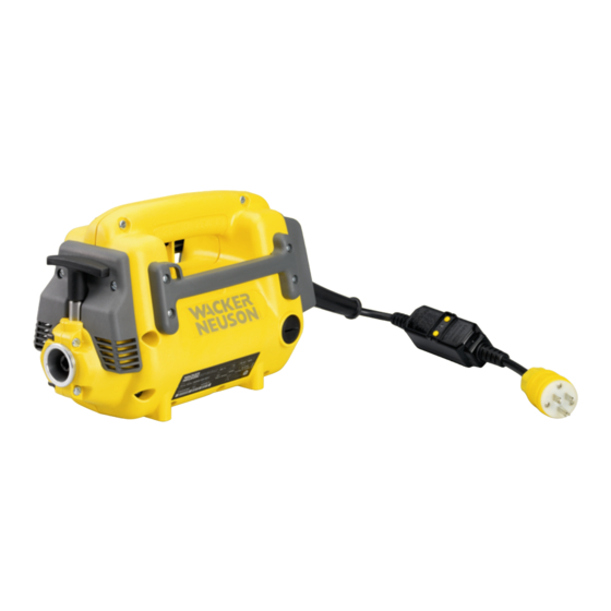
- Page 1 Operator´s manual Drive motor M1000, M2000, M3000 for modular internal vibrator HMS 07.2013 5100002951en / 002...
- Page 2 Manufacturer Wacker Neuson Produktion GmbH & Co. KG Preußenstraße 41 80809 München www.wackerneuson.com Tel.: +49-(0)89-354 02-0 Fax: +49-(0)89-354 02-390 Translation of the original operator's manual in German...
-
Page 3: Table Of Contents
Foreword ........................5 Introduction ....................... 6 Means of representation for this operator's manual ............6 Wacker Neuson representative..................7 Described machine types....................7 Identification of the machine ..................8 Safety ......................... 9 Principle ......................... 9 Qualification of the operating personnel............... 12 Protective gear ...................... - Page 4 11.2 Maintenance schedule....................42 11.2.1 Drive motor ...................... 42 11.2.2 HMS......................... 42 11.3 Maintenance work ......................43 11.3.1 Clean HMS ...................... 44 11.3.2 Drive motor ...................... 45 11.3.3 Flexible shaft ....................48 11.3.4 Vibrator head ....................51 Malfunctions ......................54 Allowable combination ...................
-
Page 5: Foreword
Foreword This operator's manual contains information and procedures for the safe opera- tion and maintenance of your Wacker Neuson machine. In the interest of your own safety and to prevent accidents, you should carefully read through the safety information, familiarize yourself with it and observe it at all times. -
Page 6: Introduction
2 Introduction Introduction Means of representation for this operator's manual Warning symbols This operator's manual contains safety information of the categories: DANGER, WARNING, CAUTION, NOTICE. They should be followed to prevent danger to life and limb of the operator or dam- age to equipment and exclude improper service. -
Page 7: Wacker Neuson Representative
This symbol is used for lists. Wacker Neuson representative Depending on your country, your Wacker Neuson representative is your Wacker Neuson service, your Wacker Neuson affiliate or your Wacker Neuson dealer. You can find the addresses in the Internet at www.wackerneuson.com. -
Page 8: Identification Of The Machine
2 Introduction Identification of the machine Nameplate data The nameplate lists information that uniquely identifies your machine. This infor- mation is needed to order spare parts and when requesting additional technical information. Enter the information of your machine into the following table: Item Designation Your information... -
Page 9: Safety
Connecting non-authorized components. Operating without a flexible shaft and vibrator head. Other special applications must be checked and released by Wacker Neuson. Its proper use also includes the observance of all instructions contained in this operator's manual as well as complying with the required service and mainte- nance instructions. - Page 10 Installation of accessories which are not from Wacker Neuson. It is no problem to install spare parts from Wacker Neuson. It is no problem to install accessories that are available in the Wacker Neuson product range of your machine. Please refer to the installation regulations in this operator's manual.
- Page 11 Have damaged or defective components replaced immediately! For further information, refer to chapter Troubleshooting. Spare parts, accessories Use only spare parts from Wacker Neuson or such that are equivalent to the orig- inal parts in design and quality. Only use accessories from Wacker Neuson.
-
Page 12: Qualification Of The Operating Personnel
3 Safety Country-specific regulations Observe the country-specific regulations, standards and guidelines in reference to accident prevention and environmental safety, for example those pertaining to hazardous materials and wearing protective gear. Complement the operator's manual with additional instructions taking into ac- count the operational, regulatory, national or generally applicable safety guide- lines. -
Page 13: Protective Gear
3 Safety Work recommendations Please observe the recommendations below: Work only if you are in a good physical condition. Work attentively, particularly as you finish. Do not operate the machine when you are tired. Carry out all work calmly, circumspectly and carefully. Never operate the machine under the influence of alcohol, drugs or medica- tion. -
Page 14: Transport
When wearing ear protection while working, you must pay attention and exercise caution because your hearing is limited, e.g. in case someone screams or a sig- nal tone sounds. Wacker Neuson recommends that you always wear ear protection. Transport Switching off the machine Before you transport the machine, switch it off and pull the plug out of the plug receptacle. - Page 15 3 Safety Work environment Familiarize yourself with your work environment before you start work. This in- cludes e.g. the following items: Obstacles in the work and traffic area. Load-bearing capacity of the ground. The measures needed to cordon off the construction site from public traffic in particular.
- Page 16 3 Safety Caution with movable parts of the HMS Keep your hands, feet and loose clothing away from moving or rotating vibrator head (Components of the HMS). Do not use components of to HMS for climbing on or holding onto Never use the protective hose, power cable or other components of the HMS for climbing on or holding onto.
-
Page 17: Safety During The Operation Of Hand Machines
3 Safety Safety during the operation of hand machines Safe working with hand machines While working, always hold the machine on the handle provided. Setting the hand machine down properly Set the machine down carefully. Do not drop the machine to the floor or from greater heights. - Page 18 I, see chapter Technical data). Only use tested extension cables which are suitable for use at construction sites: Average rubber hose H05RN-F or better – Wacker Neuson recommends H07RN-F, an SOOW cable, or a country-specific equivalent design. Immediately replace damaged extension cables (e.g. tears in the sheathing) or loose plugs and couplings.
-
Page 19: Safety During The Operation Of Modular Internal Vibrator
Service and maintenance work must only be carried out to the extent described in these operating instructions. All additional work, e.g., the replacement of the power cable, must be carried out by the Wacker Neuson representative to pre- vent any safety risks. - Page 20 3 Safety Cleaning Always keep the machine clean and be sure to clean it each time you have fin- ished using it. Do not use gasoline or solvents. Danger of explosion! Do not use high pressure washers. Permeating water can damage the machine. When electrical equipment is present, this can pose a serious injury risk from electric shocks.
-
Page 21: Safety And Information Labels
4 Safety and information labels Safety and information labels Your machine has adhesive labels containing the most important instructions and safety information. Make sure that all the labels are kept legible. Replace any missing or illegible labels. The item numbers for the labels are in the parts book. 100_0101_ls_0006.fm... - Page 22 4 Safety and information labels Item Label Description Warning Read operator´s manual to reduce risk of injury. Wear ear protection. Keep in operative position. Warning of hot surface. Warning Follow these important warnings to en- sure proper operation and to reduce shock or fire hazard.
- Page 23 4 Safety and information labels Item Label Description Warning 1. To ensure protection against electrc shock, test the device befor each use. When test button is pushed in the indi- cator light should go off. Reactivate the device by pushing the reset button an release.
- Page 24 4 Safety and information labels Item Label Description UL label. GROUND FAULT CIRCUIT INTER- RUPTER 2 POLE UNIT GFA15 AUTO RESET CLASS A RATING. 120VAC 60HZ 15A 1800W LEVITON MFG, CO.INC 100_0101_ls_0006.fm...
-
Page 25: Scope Of Delivery
5 Scope of delivery Scope of delivery The scope of delivery includes: Drive motor. Operator's manual. Parts book. General safety instructions. The HMS consists of several components (see the Technical Data chapter): Drive motor. Flexible shaft (optional). Vibrator head (optional). Note: The components that are marked as "optional"... -
Page 26: Structure And Function
6 Structure and function Structure and function Application Use the machine only as intended, see chapter Safety, Proper use. Field of application The drive motor may only be used for the operation of flexible shafts and vibrator heads. The combined HMS may be used for the following tasks: Compaction of fresh concrete. -
Page 27: Components And Operator's Controls
7 Components and operator's controls Components and operator's controls Drive components and operator's controls Item Designation Item Designation ON/OFF switch Air intake Handle Carbon brushes Side handle Air outlet GFCI (Fault current protective T-handle switch) Side handle Each of the two side handles has an eye, to which a carrying belt (accessory) can be attached. -
Page 28: Components Of The Hms
7 Components and operator's controls Carbon brushes The carbon brushes wear out during operation. If the carbon brushes are below the minimum length, the motor shuts off automatically. Components of the HMS Depending on the working conditions, you may be able to combine these com- ponents in a variety of configurations. -
Page 29: Flexible Shaft Components (Optional)
7 Components and operator's controls Flexible shaft components (optional) Item Designation Item Designation Connection to drive motor Bend protection Coupling Connection to vibrator head Vibrator head components (optional) Item Designation Item Designation Connecting piece Shaft core adapter 100_0101_cp_0009.fm... -
Page 30: Transport
8 Transport Transport WARNING Improper handling can result in injury or serious material damage. Read and follow all safety information of this operator's manual, see chapter Safety. WARNING Hot vibrator head. Touching it can cause burns. Only touch the vibrator head once the engine has cooled down. Wear protective gloves. -
Page 31: Mounting The Hms
9 Mounting the HMS Mounting the HMS Pre-assembly the vibrator head WARNING Rotating parts. Risk of injury to hands. Shut off drive. Disconnect the flexible shaft from the drive. Working in the workshop Perform maintenance work in a workshop on a workbench. This has the following benefits: Protection of the machine of contamination on the construction site. - Page 32 9 Mounting the HMS Coupling the flexible shaft to the drive Item Designation Flexible shaft Coupling 1. Switch off the drive motor via the ON/OFF switch. 2. Pull the plug from the plug receptacle. 3. Set drive motor on the floor.. 4.
-
Page 33: Use And Operation
The vibrator head is screwed on to the flexible shaft. The flexible shaft (incl. vibrator head) is connected to the drive motor. Note: For longer flexible shafts, Wacker Neuson recommends the use of a car- rying belt (accessory). Checking the machine Check the HMS and all components for damages. -
Page 34: Starting Up
10 Use and operation 10.2 Starting up Connecting the HMS to the power supply NOTICE Electrical voltage. Incorrect voltage can cause damage on the machine. Check if the voltage of the current source corresponds with the information of the machine, see chapter Technical Data. WARNING Electrical voltage. - Page 35 10 Use and operation WARNING Danger of electric shock! Serious injuries from electric shock. The GFCI does not protect against: Electric shocks resulting from short circuits between hot and neutral conduc- tors. Electric shocks resulting from possible defects or faults in an extension cord or other wiring supplying the GFCI.
- Page 36 10 Use and operation Checking the GFCI for proper functioning 1. Turn off ON/OFF switch. Note: When the ON/OFF switch is pressed, the HMS starts to run imme-dia- tely at the connection. The Vibrator head can strike out and may injure per- sons or be damaged.
- Page 37 10 Use and operation Switching on the machine Item Designation ON/OFF switch 1. Hold the machine in one hand. 2. With the other hand, pick up the protective hose so that the vibrator head does not thrash about. 3. Switch on the machine via the ON/OFF switch. Note: For flexible shafts over 2 m, ask a helper to pick up the vibrator head off the floor by the protective hose in order to prevent damage to the machine or the ground.
- Page 38 10 Use and operation Compacting fresh concrete 1. Quickly immerse the vibrator head in the fresh concrete, hold it for several se- conds and slowly pull it out again. 2. Immerse the vibrator head in all areas of the formwork and compact the fresh concrete.
-
Page 39: Decommissioning
10 Use and operation 10.3 Decommissioning Switching off the machine CAUTION The vibrator head moves if it is turned on and not immersed in the fresh con- crete. Danger of injury or danger of damage to property by uncontrolled vibrator head. Switch the machine off before you put it down. - Page 40 10 Use and operation Cleaning the machine All components of the HMS must be cleaned after each use. 1. Clean the vibrator head and flexible shaft with water. Note: You can remove concrete residue when the machine is running by im- mersing the vibrator head in gravel.
-
Page 41: Maintenance
The maintenance tasks described in this operator's manual may be performed by any responsible user unless otherwise stated. Some maintenance tasks may only be performed by specially trained personnel or by the service staff of your Wacker Neuson contact — these are specifically noted. 100_0101_mt_0007.fm... -
Page 42: Maintenance Schedule
Air vents on the air outlet. Clean the filter element. Check carbon brushes – re- place if necessary. * Have these tasks carried out by the service department of your Wacker Neuson contact person. 11.2.2 HMS Task Daily be- Every... -
Page 43: Maintenance Work
Check wear dimensions of the vibrator head. Lubricate flexible shaft and replace plastic bushing. Change oil in vibrator head. * * Have these tasks carried out by the service department of your Wacker Neuson contact person. 11.3 Maintenance work Working in the workshop Perform maintenance work in a workshop on a workbench. -
Page 44: Clean Hms
11 Maintenance 11.3.1 Clean HMS After use, clean HMS. Note: Do not clean the machine with high pressure washers or steam jet clean- ers! Wipe the drive motor and the with a damp and clean cloth. Flexible shaft Clean the ventilation slots with a suitable non-metallic tool. Clean the vibrator head and protective hose with water. -
Page 45: Drive Motor
11 Maintenance 11.3.2 Drive motor Clean the filter element Item Designation Item Designation Screw Filter element 1. On/Off-switch OFF. 2. Wait until the HMS has come to a complete standstill. 3. Pull the plug from the plug receptacle. 4. Loosen the screw and remove the cover. 5. - Page 46 11 Maintenance Checking/replacing the carbon brushes WARNING Improper replacement of parts. Danger of electrocution. Only a qualified electrician is permitted to replace parts and perform a sub- sequent safety check according to the directives in effect. Item Designation Item Designation Carbon brushes O-ring Minimum length 10mm (0.4 in)
- Page 47 11 Maintenance Checking the carbon brushes Check that both carbon brushes are at least the minimum length. Note: If one carbon brush is smaller than the minimum length, both carbon brushes must be replaced. Inserting the carbon brushes 1. Install carbon brush (on both sides of drive motor). Pay attention to the origi- nal position and location of used carbon brushes, to avoid damage and spar- king on the collector.
-
Page 48: Flexible Shaft
11 Maintenance 11.3.3 Flexible shaft Removing the shaft core Item Designation Item Designation Flexible shaft Coupling Shaft core 1. Remove any dirt around the coupling. 2. Clamp flexible shaft in a vice with prism jaws. 3. Unscrew coupling with large pipe wrench or special wrench (accessory). 4. - Page 49 11 Maintenance Replacing the plastic bushing Item Designation Item Designation Flexible shaft Retaining clip Plastic bushing 1. Remove retaining clip with a screwdriver. 2. Pull out plastic bushing with a pulling tool if necessary. 3. Wipe off bearing surface with a clean, lint-free cloth. 4.
- Page 50 11 Maintenance Lubricating the shaft core Item Designation Shaft core Protective hose Note: If the flexible shaft is damaged or has grooves, the flexible shaft must be replaced. Lubricate the shaft core thinly and uniformly with special lubricant (accesso- ries) using your hands. Assembling the flexible shaft 1.
-
Page 51: Vibrator Head
Minimum width across flats (HA vibrator head). Wear is highest at the end of the vibrator head. Let the lower tube be exchanged by your Wacker Neuson contact if the wear di- mensions are reached at a certain point. Vibrator head... - Page 52 11 Maintenance Changing the oil in the vibrator head Item Designation Item Designation Housing Shaft core adapter Connecting piece Opening the vibrator head 1. Remove any dirt around the connecting piece. 2. Clamp flexible shaft in a vice with prism jaws. 3.
- Page 53 11 Maintenance Assembling the vibrator head 1. Place pipe thread seal on the thread of the housing. 2. Screw the housing on the connecting piece and tighten with a large pipe wrench. 3. Place pipe thread seal on the thread of the flexible shaft. 4.
-
Page 54: Malfunctions
12 Malfunctions 12 Malfunctions Please refer to the following table if the machine does not work properly. It con- tains potential faults, their causes and remedies. Malfunction Cause Remedy HMS not in operation. Power supply is interrupted. Check power cable and GFCI, have it re-placed if defective. - Page 55 Have the machine repaired. * Plug is defective. Have the machine repaired. * Control lamp is defective. Have the machine repaired. * * Have these tasks carried out by the service department of your Wacker Neuson representative per- son. 100_0101_ts_0006.fm...
-
Page 56: Allowable Combination
13 Allowable combination 13 Allowable combination You can combine these components in various designs depending upon the con- ditions of use. 13.1 Drive motor – Flexible shafts – Vibrator head NOTICE A vibrator head which is too large or flexible shaft which is too long overloads the drive. - Page 57 13 Allowable combination Vibrator Drive motor Flexible shafts head SM0-S SM1-S SM2-S SM3-S SM4-S SM5-S SM7-S SM9-S H 35 M 1000 — — H 35S M 2000 M 3000 H 35HA M 1000 — — — — — — — —...
-
Page 58: Disposal
14 Disposal 14 Disposal 14.1 Disposal of waste electrical and electronic equipment For customers in EU countries This device is subject to the European Directive 2002/96/EC on waste electrical and electronic equipment (WEEE) and the corresponding national legislation. The WEEE directive outlines the procedure for handling electrical waste equip- ment across the EU. -
Page 59: Accessories
The pipe thread seal is needed for sealing the thread connection between the vi- brator head and the flexible shaft, as well as between coupling and flexible shaft. 15.3 Special lubricant for flexible shafts The Wacker Neuson special lubricant is needed for lubricating flexible shaft cores in the flexible shafts. 15.4 SS-adapter The SS-adapter is used to connect two S-flexible shafts. -
Page 60: Carrying Belt For The Drive Motor
15 Accessories 15.5 Carrying belt for the drive motor WARNING Improper use of accessories can result in injury or serious material damage. Only fasten the carrying belt to the rear handle of the drive. For longer flexible shafts, use a carrying belt to make the work easier. You can carry the drive motor with the carrying belt, if you must often change po- sition. -
Page 61: Technical Data
16 Technical data 16 Technical data 16.1 Drive motor Designation Unit M1000/120/GFCI M2000/120/GFCI M3000/120/GFCI Item no. 5100002955 5100002956 5100002957 T-Handle (Color) Green Yellow Rated current 10,0 15,0 Rated voltage Rated frequency 50 – 60 Phases Length mm (in) 500 (19.7) -
Page 62: E-Flexible Shafts (Optional)
16 Technical data 16.2 E-Flexible shafts (optional) Designation Unit SM1-E SM2-E SM4-E Length m (ft) 1.0 (3.3) 2.0 (6.6) 4.0 (13.1) Weight kg (lb) 1.5 (3.2) 2.5 (5.5) 4.3 (9.4) 16.3 S-Flexible shafts (optional) Designation Unit SM0-S SM1-S SM2-S SM3-S Length m (ft) 0.5 (1.6) -
Page 63: Standard Vibrator Head (Optional)
16 Technical data 16.4 Standard vibrator head (optional) Designation Unit H25 S H35 S Vibration range in air mm (in) 1,1 (0.043) 0,8 (0.031) 2,2 (0.1) 1,7 (0.1) Vibrations 1/min 12,000 Vibrations Bottle shape Round Bottle diameter/diagonal mm (in) 25 (1.0) 35 (1.4) Length of vibrator head mm (in) -
Page 64: Ha-Vibrator Head (Optional)
16 Technical data 16.5 HA-Vibrator head (optional) Designation Unit H25HA H35HA H45HA H50HA Vibration range in air mm (in) 2,1 (0.1) 2,1 (0.1) 3,0 (0.1) 3,5 (0.1) Vibrations 1/min 12.000 Vibrations Bottle shape Square Bottle diameter/diagonal mm (in) 26 (1.0) 36 (1.4) 45 (1.8) 50 (2.0) -
Page 65: Extension Cable
< 35 < 55 Example You utilize an M1000/120 and want to use an extension cable with a length of 25 m. The machine has an input voltage of 120 V. According to the table, the extension cable must feature a cross-section area of 2.5 mm... - Page 66 16 Technical data US Machine Machine Voltage Extension Cross-section area of cable M1000 120 1~ < 90 < 142 < 224 M2000 120 1~ < 60 M3000 < 95 < 149 < 235 100_0101_td_0011.fm...
-
Page 67: Glossary
17 Glossary 17 Glossary Class rating The class rating according to DIN EN 61140 specifies the safety measures for electrical equipment to avoid electrocution. There are four class ratings: Class rating Meaning No special protection apart from the basic insulation. No grounded conductor. - Page 68 17 Glossary Protection class IP The protection class according to DIN EN 60529 indicates the suitability of elec- trical equipment for use in certain ambient conditions as well as the protection against risks. The protection class is specified by an IP code according to DIN EN 60529. Code Meaning 1st number: Protection against touching hazardous parts.
Need help?
Do you have a question about the M1000 and is the answer not in the manual?
Questions and answers