
Related Manuals for Wacker Neuson M 1000


Summary of Contents for Wacker Neuson M 1000
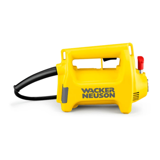
- Page 1 0154561en 0303 Internal Vibrator M 1000 M 2000 M 3000 OPERATOR’S MANUAL...
-
Page 3: Table Of Contents
Table of Contents Foreword Safety Information Service Safety ..................5 Operating Safety .................. 5 Safety & Informational Labels .............. 7 Label Locations ..................7 Technical Data Motors ....................8 Vibrator Heads ..................9 Shafts ....................10 Sound and Vibration Measurements ..........10 Operation Application .................. - Page 4 Table of Contents wc_bo0154561002enTOC.fm...
- Page 5 Foreword Foreword This manual provides information and procedures to safely operate and maintain this Wacker model. For your own safety and protection from injury, carefully read, understand and observe the safety instructions described in this manual. Keep this manual or a copy of it with the machine. If you lose this manual or need an additional copy, please contact Wacker Corporation.
-
Page 6: Safety Information
Safety Information Safety Information This manual contains DANGER, WARNING, CAUTION, and NOTE callouts which must be followed to reduce the possibility of personal injury, damage to the equipment, or improper service. This is the safety alert symbol. It is used to alert you to potential personal injury hazards. -
Page 7: Service Safety
Safety Information Service Safety When using electric tools, basic safety precautions should always be followed to reduce the risk of fire, electric shock, and personal injury! The guidelines following will help the user maintain operator safety. DANGER 2.1.1 NEVER use worn electrical cords. Severe electrical shock and equipment damage may result. - Page 8 Safety Information 2.2.8 Goggles or safety glasses will protect against eye damage caused by flying debris. 2.2.9 NEVER carry motor by cord or pull on it to disconnect it from receptacle. Keep cord away from heat, oil and sharp edges. 2.2.10 Keep handle, and other areas where motor and shaft are gripped, dry, clean and free from oil and grease.
-
Page 9: Safety & Informational Labels
Safety Information Safety & Informational Labels Wacker machines use international pictorial labels where needed. These labels are described below: Label Meaning Wear eye, ear, and head protection when operating machine. Read the operator's manual for machine infor- mation. Label Locations C A U T I O N F O R S A F E O P E R A T I O N R E A D w c _ g r 0 0 1 2 0 8... -
Page 10: Technical Data
Technical Data Technical Data Motors Item No. M 1000 (Green) M 2000 (Yellow) M 3000 (Red) Motors Voltage (AC/DC) Current (Maximum) Power kW (Hp) 1.0 (1.3) 1.0 (1.3) 1.7 (2.3) 1.5 (2.0) 2.3 (3.1) 2.3 (3.1) Speed (No-load) 15500 17500... -
Page 11: Vibrator Heads
Technical Data Vibrator Heads Item No. H25S H35S H45S Vibrator Heads Diameter (in.) (1.0) (1.0) (1.4) (1.4) (1.8) (1.8) (2.3) (2.5) Length (in.) (17.3) (11.7) (16.2) (12.3) (15.3) (12.0) (16.1) (15.3) Weight (lbs.) (2.6) (1.8) (4.6) (3.6) (7.1) (5.6) (10.8) (13.4) Compaction Dia. -
Page 12: Shafts
Technical Data Shafts Item No. SM1-E SM2-E SM4-E E - Shafts Length (ft.) (6.5) (13) Weight (lbs.) (10) Lubrication WACKER Flex-shaft Lube - P/N 26880 Item No. SM0-S SM1-S SM2-S SM3-S SM4-S SM5-S SM7-S SM9-S S - Shafts Length (ft.) (1.5) (6.5) (10) -
Page 13: Operation
Operation Operation Application The HMS series of internal vibrators can be used over a wide range of applications for the consolidation of concrete. WACKER internal vibrators are typically used for on-site vibration of concrete for foundations, walls, columns, slab work, etc. Additional in- plant applications include vibration of concrete during the production of pipes, slabs, beams, double T columns, walls, etc. -
Page 14: Recommended Hms Combinations
1 (3) 2 (6.5) 3 (10) 4 (13) 5 (16.5) 7 (23) 9 (29.5) Head (c) Motor (a) H 25 M 1000 M 2000 M 3000 H 35 M 1000 M 2000 M 3000 H 45 M 2000 M 3000... -
Page 15: Extension Cords
Table 2 Minimum wire size for extension cords - AWG (mm MAXIMUM CORD LENGTH - m (ft.) 7.5 (25) 15 (50) 30 (100) 45 (150) 55 (175) 60 (200) 115V M 1000 1.5 (16) 1.5 (16) 2.5 (14) 2.5 (14) 4 (12) 4 (12) M 2000 1.5 (16) 1.5 (16) -
Page 16: Connecting Motor To Power Supply
Operation Connecting Motor to Power Supply See Graphic: wc_gr001211 To reduce the risk of electric shock, motors equipped with 3-wire grounded plugs must be properly grounded. On these motors use only 3-wire grounded plugs, receptacles, and extension cords. WARNING 4.4.1 Check that switch on motor is off before connecting motor to power source. -
Page 17: Assembling Head, Motor And Shaft
Operation Assembling Head, Motor and Shaft See Graphic: wc_gr001212, wc_gr001247 4.5.1 H Heads: Apply pipe sealant to threads on head (a). Attach head onto end of flexshaft (left hand thread) and tighten using a wrench. HR Heads: Slide the casing coupling protective sleeve (d) onto the end of the shaft. -
Page 18: Operation
Operation Operation Hold head in air or place it on soft surface when starting motor. This will prevent it from bouncing on hard surfaces which could damage bearings. During use, insert the head quickly into the mix and then pull it out slowly. -
Page 19: Maintenance
Maintenance Maintenance Periodic Maintenance Every Every Every Before starting hrs. hrs. hrs. Inspect air filter and vent holes. Clean or • replace dirty or clogged filters. Inspect electrical cords for wear or damage. • Do not use damaged cords. Inspect brushes in motor. •... -
Page 20: Motor Brushes
Maintenance Motor Brushes See Graphic: wc_gr001213 To protect the motor, the brushes are designed to automatically shut off the motor if they become too short. If the motor stops during operation, the brushes may need to be replaced. To avoid having the brushes shut down the motor unexpectedly, inspect brushes every 50 hours and replace them when necessary. -
Page 21: Motor Housing
Maintenance Motor Housing See Graphic: wc_gr001214 Clean motor housing immediately after use, using a damp cloth to remove dust or concrete. Inspect rear air filter, front screen, and vents on motor housing to make sure they are open. Replace or clean clogged air filter before operating motor to prevent overheating. -
Page 22: Lubricating Shaft
Maintenance Lubricating Shaft See Graphic: wc_gr001215 Remove wire core (f) from shaft casing and wipe with a clean cloth. Apply a liberal amount of flex-shaft grease to the entire length of the core by hand (g). Insert core into casing and rotate it. Repeat this procedure several times. -
Page 23: Lubricating H-Head
Maintenance Lubricating H-Head See Graphic: wc_gr001216 The bearings in the head are lubricated with oil. To extend bearing life, change oil in head every 300 hours of operation. To change oil: Place head in a vise and remove tip from casing. If necessary, add a couple of small spot welds (h) on tip to provide a better grip for wrench. -
Page 24: Checking H-Head For Wear
Maintenance Checking H-Head for Wear See Graphic: wc_gr001217 Periodically measure the outside diameter of the head casing (a) in the area of most noticeable wear. Replace head if measured diameter is less than the minimum wear diameter. MINIMUM DIAMETER WEAR DIAMETER mm (in.) mm (in.) H 25... -
Page 25: Troubleshooting
Maintenance Troubleshooting Problem / Symptom Reason / Remedy Motor does not start. • Open circuit breaker or blown fuse on power supply. • Brushes are worn too short. Replace. • Switch on motor bad or wire connections loose. Motor runs at normal speed •... -
Page 26: Wiring Schematics
Maintenance Wiring Schematics See Graphic: wc_gr001218 M 1000 M 2000 M 3000 115V 5843 6305 5845 7159 7653 230V 5041 6551* 5800 * NO GROUND WIRE SWITCH B BLACK or BROWN STATOR G GREEN or GREEN W/ YELLOW STRIPE ROTOR... - Page 27 Maintenance See Graphic: wc_gr001219 M 1000 M 2000 5494 5432 230V 5495 SWITCH B BLACK or BROWN STATOR G GREEN or GREEN W/ YELLOW STRIPE ROTOR W WHITE or BLUE LH BRUSH Y YELLOW RH BRUSH RFI CAPACITOR INDUCTION COIL w c _ g r 0 0 1 2 1 9 wc_tx000266gb.fm...
- Page 28 Maintenance See Graphic: wc_gr001220 M 3000 6590 230V SWITCH B BLACK or BROWN STATOR G GREEN or GREEN W/ YELLOW STRIPE ROTOR W WHITE or BLUE LH BRUSH Y YELLOW RH BRUSH L BLUE RFI CAPACITOR INDUCTION COIL w c _ g r 0 0 1 2 2 0 wc_tx000266gb.fm...
Need help?
Do you have a question about the M 1000 and is the answer not in the manual?
Questions and answers