Table of Contents
Advertisement
Advertisement
Table of Contents
Troubleshooting

Related Manuals for Wacker Neuson WM 80


Summary of Contents for Wacker Neuson WM 80
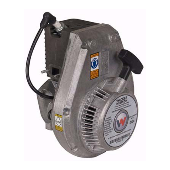
- Page 1 Repair Manual Engine WM 80 0162695en 0610...
- Page 2 This publication may be photocopied by the original purchaser of the machine. Any other type of reproduction is prohibited without express written permission from Wacker Neuson Corporation. Any type of reproduction or distribution not authorized by Wacker Neuson Corporation represents an infringement of valid copyrights. Violators will be prosecuted. Trademarks All trademarks referenced in this manual are the property of their respective owners.
-
Page 3: Foreword
Use the separate Parts Book supplied with the machine to order replacement parts. If you are missing any of these documents, please contact Wacker Neuson Corporation to order a replacement or visit www.wackerneuson.com. When ordering parts or requesting service information, be prepared to provide the machine model number, item number, revision number, and serial number. - Page 4 Foreword wc_tx001528gb.fm...
-
Page 5: Table Of Contents
WM 80 Table of Contents Foreword Safety Information Signal Words Used in this Manual ............9 Safety Guidelines for Operating the Machine ........10 Operator Safety while Using Internal Combustion Engines ....12 Service Safety ..................13 Technical Data Engine Specifications ................. 14 Tune-up Specifications ............... - Page 6 Table of Contents WM 80 Inspecting the Starter ................32 Assembling the Starter ................33 Replacing the Starter Rope ..............34 Ignition System Diagram ..............36 Ignition System Operation ..............37 Checking Spark ...................38 Using Ignition Tester ................39 4.10 Setting Air Gap ..................40 4.11 Replacing the Ignition Module .............42 Carburetor Basics Brands Used ..................46...
- Page 7 Ordering Parts .................. 105 10.4 Reference Numbers ( ) ..............105 10.5 Threadlocking Compounds .............. 105 10.6 Removing the WM 80 Engine from BS Rammers (auto-release choke models) .................. 106 10.7 Removing Engine From BS Model Rammers (standard choke models) ..............108 10.8 Removing Engine From BH 23 Breakers .........
- Page 8 Table of Contents WM 80 10.21 Crankshaft Bearings ................132 10.22 Bearing Installation ................134 wc_br0162695en_003TOC.fm...
-
Page 9: Safety Information
WM 80 Safety Information Safety Information Signal Words Used in this Manual This manual contains DANGER, WARNING, CAUTION, NOTICE, and NOTE signal words which must be followed to reduce the possibility of personal injury, damage to the equipment, or improper service. -
Page 10: Safety Guidelines For Operating The Machine
• Familiarize yourself with the location and proper use of all controls and safety devices. • Contact Wacker Neuson Corporation for additional training if necessary. When operating this machine: • Do not allow improperly trained people to operate the machine. - Page 11 WM 80 Safety Information 1.2.6 Never tamper with or disable the function of operating controls. 1.2.7 Never use the choke to stop the engine. 1.2.8 Never operate the machine in areas where explosions may occur. 1.2.9 Read, understand, and follow procedures in the Operator’s Manual before attempting to operate the machine.
-
Page 12: Operator Safety While Using Internal Combustion Engines
Safety Information WM 80 Operator Safety while Using Internal Combustion Engines WARNING Internal combustion engines present special hazards during operation and fueling. Failure to follow the warnings and safety standards could result in severe injury or death. Read and follow the warning instructions in the engine owner’s manual and the safety guidelines below. -
Page 13: Service Safety
1.4.11 ALWAYS clean debris from engine cooling fins. 1.4.12 Replace worn or damaged components with spare parts designed and recommended by Wacker Neuson Corporation. 1.4.13 Disconnect the spark plug on machines equipped with gasoline engines, before servicing, to avoid accidental start-up. -
Page 14: Technical Data
Technical Data WM 80 Repair Technical Data Engine Specifications Engine Model WM 80 Type 2-cycle Maximum rated power (kW) hp 3.0 (4.0) Number of cylinders Piston displacement 80 (4.9) (cu.in.) Cylinder bore mm (in.) (45) 1.77 Stroke mm (in.) 50 (1.96) -
Page 15: Tune-Up Specifications
WM 80 Repair Technical Data Tune-up Specifications Engine Model WM 80 Ring gap: mm (in.) 0.2–0.4 (0.008–0.016) mm (in.) 1.0–1.2 (0.039–0.047) Maximum Cylinder wear: mm (in.) 0.2 (0.008) Maximum bore taper Cylinder head kg/cc (psi) 8.0–9.7 (120–140) compression Ignition module air gap* mm (in.) -
Page 16: Carburetor Specifications For Bing, And Tillotson (Standard**)
Technical Data WM 80 Repair Carburetor Specifications for Bing, and Tillotson (Standard**) Machine Carburetor Low-speed jet High-speed jet Carburetor Make size (x 0.01) size (x 0.01) adapter bore diameter mm (in.) BS 45Y •Bing 8 (0.315) •Tillotson Adjustable #71* 8 (0.315) •Tillotson w/... - Page 17 WM 80 Repair Technical Data BS 500 7550 13 (0.512) Rev. 111–121 BS 500 7550 11 (0.433) Rev. >121 BS 500 8048 13 (0.512) Rev. 100–102 BS 500 8048 13 (0.512) Rev. 103–110 BS 500 8048 13 (0.512) Rev. 111–118 BS 500 8048 11 (0.433)
- Page 18 * Single-needle Tillotson carburetors only. Dual-needle Tillotson carburetors use an adjustable needle for high-speed adjustment. ** Standard sizes listed. Operation at altitudes above 3000 m (5000 feet) may require different jet and carburetor adapter sizes. Contact Wacker Neuson Neuson Service for the modifications required. wc_td000166gb.fm...
-
Page 19: Operating And Idle Speeds
WM 80 Repair Technical Data Operating and Idle Speeds Machine Idle speed ±100 rpm Full speed ±100 rpm BS 45Y 1800 4300 BS 52Y 1800 4300 BS 60Y 1800 4600 BS 62Y 1800 4500 BS 65Y 1500 4400 BS 100Y... -
Page 20: Maintenance
Maintenance WM 80 Maintenance Periodic Maintenance Schedule Daily After first Every Every Every 3 5 hours week or month or months or 25 Hours 100 Hours 300 hours Check fuel level. • Clean and/or inspect air filter (cartridge type). •... -
Page 21: Storage
WM 80 Maintenance Storage If storing the unit for a long period of time (more than 30 days) carry out the following: 3.2.1 Drain fuel from the tank. 3.2.2 Start the engine and run it until all the fuel in the carburetor is used. -
Page 22: Cartridge-Type Air Filter
Maintenance WM 80 Cartridge-Type Air Filter See Graphic: wc_gr002875 3.4.1 This type of air filter is found on rammers with Bing carburetors and on early rammers with Tillotson carburetors. To service: 3.4.2 Unsnap the spring clips on the protective cover... -
Page 23: Disc-Type Air Filter
WM 80 Maintenance Disc-Type Air Filter See Graphic: wc_gr002876 The disc-type air filter with oil-wetted foam precleaner is used on BPS 1330, BPS 1350, BVPN 50, and the BHF 30S. To service the filter: 3.5.1 Close the carburetor choke. Loosen the clamp... -
Page 24: Low-Maintenance Air Filter
Maintenance WM 80 Low-Maintenance Air Filter See Graphic: wc_gr002877 This type of air filter is found on rammers. The air filter is self-cleaning and uses the movement of the machine to shake dust and dirt loose from the air filter element while the rammer is operating. Under normal operating conditions this element will not require cleaning and should not be removed from the machine. -
Page 25: Dual-Element Air Cleaner
WM 80 Maintenance wc_gr002877 Dual-Element Air Cleaner See Graphic: wc_gr000046 NEVER use gasoline or other types of low flash-point solvents for cleaning the air cleaner. A fire or explosion could result. WARNING NOTICE: NEVER run engine without air cleaner. Severe engine damage will occur. -
Page 26: Three-Stage Air Cleaners
Maintenance WM 80 Three-Stage Air Cleaners See Graphic: wc_gr001168 NEVER use gasoline or other types of low flash point solvents for cleaning the air filter. A fire or explosion could result. WARNING NOTICE: NEVER run engine without main paper filter element (b). - Page 27 WM 80 Maintenance wc_gr001168 wc_tx000520gb.fm...
-
Page 28: Engine Cleaning
Maintenance WM 80 Engine Cleaning The WACKER WM 80 engine is air cooled and depends on the cylinder cooling fins to dissipate heat. Dirt and debris caught in the cooling fins can prevent them from dissipating heat causing the engine to overheat. - Page 29 WM 80 Maintenance 3.11.3 Clean the exhaust port using a blunt scraper. Inspect the gasket (3, 4) and replace it if torn or cracked. 3.11.4 Soak the muffler in carburetor cleaner until the carbon deposits break up. Drain the muffler and blow dry it dry with compressed air.
-
Page 30: Fuel Filter
Maintenance WM 80 3.12 Fuel Filter See Graphic: wc_gr002879 Dirt is the primary cause of carburetor problems. Unfiltered fuel can quickly plug the passages in the carburetor and cause poor performance. Two different styles of fuel filters are used with the WM 80 engine. -
Page 31: Starting And Ignition
WM 80 repair Starting and Ignition Starting and Ignition Starter Assembly Exploded View wc_gr002880 See Graphic: wc_gr002880 Description Description Starter assembly Spring Rope Ratchet wheel Handle Cover Wear plate Lock washer Return spring Locknut Starter pulley Starter housing Washer wc_tx000521gb.fm... -
Page 32: Disassembling The Starter
Starting and Ignition WM 80 repair Disassembling the Starter See Graphic: wc_gr002880 4.2.1 Remove the starter assembly from the fan cover and release the spring tension as described in section Replacing the Starter Rope. 4.2.2 Untie the rope (2) and remove the handle (3). -
Page 33: Assembling The Starter
WM 80 repair Starting and Ignition wc_gr002881 Assembling the Starter See Graphic: wc_gr002880 and wc_gr002881 4.4.1 Clean all the components of the starter before reassembling the starter. 4.4.2 Note: To reduce dirt and dust from collecting between the spring windings, avoid using grease to lubricate the tarter return spring or the inside of the reel where the spring seats. -
Page 34: Replacing The Starter Rope
Starting and Ignition WM 80 repair Replacing the Starter Rope See Graphic: wc_gr002882 The starter rope can be replaced without removing the rope reel pulley from the starter assembly. Removal: 4.5.1 Remove the starter assembly from the flywheel housing. 4.5.2 Lift the rope through the notch in the drum. - Page 35 WM 80 repair Starting and Ignition wc_gr002882 wc_tx000521gb.fm...
-
Page 36: Ignition System Diagram
Starting and Ignition WM 80 repair Ignition System Diagram wc_gr002883 wc_tx000521gb.fm... -
Page 37: Ignition System Operation
WM 80 repair Starting and Ignition Ignition System Operation See Graphic: wc_gr002883 The ignition system consists of the ignition module (a), flywheel (b), shutoff switch (c) or (d), and spark plug (e). During each engine revolution, a permanent magnet (f) embedded in the flywheel passes under the ignition module. -
Page 38: Checking Spark
Starting and Ignition WM 80 repair Checking Spark Remove the spark plug and inspect the electrode and insulator for damage. Also check electrode for proper gap. See section Tune-up Specifications. Return the spark plug to the cylinder before checking for spark. -
Page 39: Using Ignition Tester
WM 80 repair Starting and Ignition • Poor wire connections • Defective stop switch • Incorrect air gap • Weak or dead flywheel magnet • Insufficient rpm (must have 500 min.) Using Ignition Tester See Graphic: wc_gr002884 A more accurate test of the ignition module can be made using ignition tester P/N 78836 4.9.1... -
Page 40: Setting Air Gap
Starting and Ignition WM 80 repair 4.10 Setting Air Gap See Graphic: wc_gr002885 Newer engines use guide sleeve pins to automatically set the air gap; however, older models still require the proper air gap to be set manually. If the air gap is set incorrectly, the engine may be hard to start or it may run erratically. - Page 41 WM 80 repair Starting and Ignition wc_gr002885 wc_tx000521gb.fm...
-
Page 42: Replacing The Ignition Module
Starting and Ignition WM 80 repair 4.11 Replacing the Ignition Module See Graphic: wc_gr002886 Removal: The engine does not have to be removed from the machine to replace the ignition module. 4.11.1 Disconnect the ignition wire from the spark plug. - Page 43 WM 80 repair Starting and Ignition wc_gr002886 wc_tx000521gb.fm...
- Page 44 Starting and Ignition WM 80 repair See Graphic: wc_gr002887 Installation: 4.11.12 Apply a light coating of oil to the ground (a) and ignition wires (b) and slide them through the protective sleeve (c). 4.11.13 Slide the ignition wire through the boot (d) in the side of the crankcase.
- Page 45 WM 80 repair Starting and Ignition wc_gr002887 wc_tx000521gb.fm...
-
Page 46: Carburetor Basics
Carburetor Basics Brands Used See Graphic: wc_gr005089 Three brands of carburetors are used on the WM 80 engine: Walbro (1), Tillotson (2), and Bing (3). The Walbro and Tillotson carburetors have internal fuel pumps while the Bing uses gravity feed to supply the fuel from the tank to the engine. -
Page 47: Walbro Carburetor Operation
WM 80 Repair Carburetor Basics Walbro Carburetor Operation Fuel Pump The fuel pump is made up of a diaphragm (a) and a series of check valves (b & c). The power to operate the fuel pump comes from the crankcase impulse. - Page 48 Carburetor Basics WM 80 Repair Fuel Metering There are four components of the fuel metering system: the metering diaphragm (a), the metering lever (b), the spring (c), and the inlet needle (d). The metering lever transfers the pressure of the spring to the inlet needle, holding the inlet needle closed and preventing fuel flow.
- Page 49 WM 80 Repair Carburetor Basics Start up A rich fuel-to-air mixture is required at startup because of the lower cranking speed (compared to running) which causes less air flow, and the fact that the engine is usually cold. (A cold engine is not efficient at vaporizing fuel because heat is required to vaporize liquid.)
- Page 50 Carburetor Basics WM 80 Repair Idle Once the engine starts, the choke (a) is opened and the throttle (b) nearly closed. The engine is at the idle state. During idle, low pressure exists on the engine side of the throttle and atmosphere pressure (high) on the other.
- Page 51 WM 80 Repair Carburetor Basics Partial Throttle Operation At partial throttle, the choke (a) remains in the open position and the throttle (b) is partially opened. During partial throttle, low pressure exists on the engine side of the throttle plate. The low pressure draws fuel from the three progression fuel nozzles (d).
- Page 52 Carburetor Basics WM 80 Repair Wide-Open Throttle Operation At wide-open throttle, the choke (a) remains in the open position and the throttle (b) is wide open. During this state, the throttle plate has little affect on high- and low-pressure areas within the carburetor throat.
- Page 53 WM 80 Repair Carburetor Basics Air Purge System The Walbro carburetor has an air purge system. The air purge system removes air from the fuel passages so that only fuel fills the carburetor and the fuel lines. The heart of the air purge system is the bulb. The bulb works in conjunction with a number of check valves.
-
Page 54: Versions Of Tillotson Carburetor
Carburetor Basics WM 80 Repair Versions of Tillotson Carburetor See Graphic: wc_gr002889 1) Dual Needle Dual needle carburetors have mixture needle valves that are adjustable. One of the valves adjusts the high-speed jet and the other valve adjusts the low-speed jet . -
Page 55: Tillotson Carburetor Operation
WM 80 Repair Carburetor Basics Tillotson Carburetor Operation See Graphic: wc_gr002891 Fuel Pump: The Tillotson carburetor uses a flexible diaphragm fuel pump operate an inlet valve which controls fuel flow to the carburetor fuel reservoir . The fuel pump operates by reacting to pressure changes in the engine crankcase transmitted through an impulse line . - Page 56 Carburetor Basics WM 80 Repair See Graphic: wc_gr002892 Inlet Needle Valve: The inlet needle valve controls fuel flow into the fuel chamber. This valve is operated by a second diaphragm called the control diaphragm . The control diaphragm is activated by the vacuum created when air moves past the venturi of the carburetor throat.
- Page 57 WM 80 Repair Carburetor Basics See Graphic: wc_gr002893 Start-up mode (choke): During cold start-up, the choke shutter (butterfly) (k) is closed and the throttle shutter (l) is partially open. As the engine is turned over, engine suction draws fuel from the primary (m), secondary (n), and main fuel (o) discharge ports.
- Page 58 Carburetor Basics WM 80 Repair In single-needle versions (2), the throttle shutter does not open and there is no idle speed screw; instead, a small hole in the shutter regulates the air flow. The idle speed is also regulated by the slow speed mixture needle valve .
- Page 59 WM 80 Repair Carburetor Basics See Graphic: wc_gr002895 Partial Throttle: At partial throttle, the throttle shutter is partially opened, allowing a greater amount of air through the carburetor. The throttle has opened wide enough to expose the secondary idle discharge port which provides more fuel to mix with the air.
- Page 60 Carburetor Basics WM 80 Repair See Graphic: wc_gr002896 Full Throttle: The wider the throttle shutter opens, the more air that will flow through the carburetor. As the air reaches the venturi , it is forced to flow faster to keep the same volume of air flowing. The faster the air flows through the venturi, the lower the air pressure in the venturi becomes.
-
Page 61: Bing Carburetor Operation
WM 80 Repair Carburetor Basics Bing Carburetor Operation wc_gr002897 See Graphic: wc_gr002897 Fuel Feed: The Bing carburetor does not use a fuel pump; instead, the fuel supply is gravity fed. A priming button is used during the initial start-up to... - Page 62 Carburetor Basics WM 80 Repair Partial Throttle: At partial throttle, the throttle shutter is partially opened allowing a greater amount of air through the carburetor. The throttle has opened wide enough to expose the secondary-idle discharge port and the engine suction draws fuel from both the primary-idle and secondary- idle discharge ports.
- Page 63 WM 80 Repair Carburetor Basics Notes wc_tx000522gb.fm...
-
Page 64: Carburetor Adapters
When used in combination with the carburetor fuel jets, the power and speed of the engine is controlled. This allows the WM 80 engine to adapt to the power and speed requirements of different machine models. - Page 65 WM 80 Repair Carburetor Basics wc_gr007414 wc_tx000522gb.fm...
-
Page 66: Carburetor Replacement
Carburetor Replacement WM 80 Repair Carburetor Replacement Replacing the Walbro Carburetor (auto-release choke models) Removal 6.1.1 Stop the machine and allow it to cool. 6.1.2 Remove the carburetor guard 6.1.3 Loosen the hose clamp and remove the air duct 6.1.4 Disconnect the ignition wire from the spark plug. - Page 67 WM 80 Repair Carburetor Replacement Continued from the previous page. 6.1.7 Have a container ready, then remove the oil hose and drain it. 6.1.8 Make sure the throttle is in the OFF position. This position also closes the fuel valve. Then, remove the fuel hose and drain it.
- Page 68 Carburetor Replacement WM 80 Repair Installation Perform the procedure below to install the carburetor 6.1.1 Assemble the adapter , lower gasket , flange and upper (k), gasket to the carburetor Note: The gaskets are not interchangeable. 6.1.2 Connect the oil hose , and the fuel hose , to the carburetor.
- Page 69 WM 80 Repair Carburetor Replacement 6.1.4 Slide the throttle cable through the adapter and reconnect it to the clamp wc_gr007456 6.1.5 Install the air duct with the hose clamp. 6.1.6 Using Loctite® 243 on the screws, install the carburetor guard Result The installation procedure is now complete.
-
Page 70: Removing Walbro Carburetor (Standard Choke Models)
Carburetor Replacement WM 80 Repair Removing Walbro Carburetor (standard choke models) 6.2.1 Stop the machine and allow it to cool. 6.2.2 Place the throttle in the OFF position. 6.2.3 Disconnect the ignition wire from the spark plug. 6.2.4 Remove the carburetor guard 6.2.5... - Page 71 WM 80 Repair Carburetor Replacement Notes wc_tx000522gb.fm...
-
Page 72: Removal, Tillotson With Composite Adapter
Carburetor Replacement WM 80 Repair Removal, Tillotson with composite adapter See Graphic: wc_gr002929 6.3.1 Stop the machine and allow it to cool. 6.3.2 Close the fuel valve (a) (if equipped). 6.3.3 Disconnect the ignition wire (b) at the spark plug. - Page 73 WM 80 Repair Carburetor Replacement wc_gr002929 wc_tx000522gb.fm...
-
Page 74: Tillotson With Straight-Through Adapters
Carburetor Replacement WM 80 Repair Tillotson with Straight-Through Adapters See Graphic: wc_gr002898 6.4.1 Turn off the fuel valve at the tank and disconnect the spark plug lead wire. 6.4.2 Remove the air filter pipe (loosen both clamps). 6.4.3 Disconnect the throttle cable. -
Page 75: Bing
WM 80 Repair Carburetor Replacement wc_gr002899 wc_gr002900 Bing See Graphic: wc_gr002900 6.6.1 Turn off the fuel valve at the tank and disconnect the spark plug lead wire. 6.6.2 Remove the air filter pipe (loosen both clamps). 6.6.3 Disconnect the throttle cable. -
Page 76: Carburetor Overhaul
Carburetor Overhaul WM 80 Repair Carburetor Overhaul Walbro Carburetor Exploded View (auto-release choke models) wc_tx000522gb.fm... -
Page 77: Walbro Carburetor Components (Auto-Release Choke Models)
WM 80 Repair Carburetor Overhaul Walbro Carburetor Components (auto-release choke models) Description Description Screw Screw Cover Screw Gasket Cover Diaphragm Bulb Screen Valve Washer Air purge body assembly Spring Diaphragm Choke shaft Gasket Spacer Nozzle Throttle lever Spring Screw Needle... -
Page 78: Rebuilding The Walbro Carburetor (Auto-Release Choke Models)
Carburetor Overhaul WM 80 Repair Rebuilding the Walbro Carburetor (auto-release choke models) Disassembly 7.3.1 Remove the cover from the fuel-pump side of the carburetor. 7.3.2 Remove the fuel pump diaphragm and gasket 7.3.3 Remove the bracket and the air purge bulb . - Page 79 WM 80 Repair Carburetor Overhaul 7.3.7 Remove the shutter (butterfly). 7.3.8 Remove the screw , lever , washer , and spacer 7.3.9 Remove the retaining ring , then remove the choke shaft 7.3.10 Remove the shutter (butterfly) from the throttle shaft.
-
Page 80: Table Of Contents Wm
Carburetor Overhaul WM 80 Repair 7.3.13 Non-EPA regulated countries only. Remove the high- and low-speed needle valves wc_gr005125 7.3.14 Using a punch, remove the Welch plug 7.3.15 Non-EPA regulated countries only. Press out the main nozzle (zz) 7.3.16 Remove the screen(s) - Page 81 WM 80 Repair Carburetor Overhaul Reassembly 7.3.1 Align the hole in the main nozzle with the passage of the high- (zz) speed needle. Press the main nozzle into the carburetor body until the top of the main nozzle is flush with the carburetor body.
- Page 82 Carburetor Overhaul WM 80 Repair Continued from the previous page. 7.3.7 Install the shutter (butterfly). 7.3.8 Install the spring and washer on the choke shaft, then install the choke shaft into the carburetor body. 7.3.9 Align the spring as shown, then secure the choke shaft with...
- Page 83 WM 80 Repair Carburetor Overhaul Continued from the previous page. 7.3.12 Install the screw , metering lever , pin , spring , and inlet needle 7.3.13 Install the metering diaphragm 7.3.14 Install the combination valve into the air purge body assembly then install the air purge body assembly.
-
Page 84: Walbro Carburetor Exploded View (Standard Choke Models)
Carburetor Overhaul WM 80 Repair Walbro Carburetor Exploded View (standard choke models) wc_gr005118 wc_tx000522gb.fm... -
Page 85: Walbro Carburetor Components (Standard Choke Models)
WM 80 Repair Carburetor Overhaul Walbro Carburetor Components (standard choke models) Description Description Screw Bulb Cover Combination valve Gasket Air purge body assembly Diaphragm Diaphragm Screen Gasket Washer Nozzle Spacer Idle needle Lever Power needle Screw Spring Inlet needle Screw... -
Page 86: Rebuilding The Walbro Carburetor (Standard Choke Models)
Carburetor Overhaul WM 80 Repair Rebuilding the Walbro Carburetor (standard choke models) Disassembly 7.6.1 Remove the cover from the fuel-pump side. 7.6.2 Remove the fuel pump diaphragm and gasket 7.6.3 Remove the bracket and the air purge bulb . Separate the bulb from the bracket. - Page 87 WM 80 Repair Carburetor Overhaul 7.6.7 Remove the shutter (butterfly). 7.6.8 Remove the choke shaft and spacer . Also remove the ball and the spring from the carburetor body. 7.6.9 Remove the throttle lever , spacer , and washer 7.6.10 Remove the shutter...
- Page 88 Carburetor Overhaul WM 80 Repair 7.6.13 Non-EPA regulated countries only. Press out the main nozzle (zz) The procedure is now complete. Reassembly 7.6.1 Align the hole in the main nozzle with the passage of the high- (zz) speed needle. Press the main nozzle into the carburetor body until the top of the main nozzle is flush with the carburetor body.
- Page 89 WM 80 Repair Carburetor Overhaul wc_gr005128 7.6.4 Install the spring to the throttle shaft . Install the throttle shaft into the carburetor body and install the shutter (butterfly). This procedure continues on the next page. wc_tx000522gb.fm...
- Page 90 Carburetor Overhaul WM 80 Repair Continued from the previous page. 7.6.5 Install the washer , spacer , and the throttle lever . Note the positioning of the throttle lever compared to the throttle shaft wc_gr005130 7.6.6 Install the spring and ball .
- Page 91 WM 80 Repair Carburetor Overhaul Continued from the previous page. 7.6.10 Install the combination valve . Install the air purge body assembly , bracket, and air purge bulb 7.6.11 Install the new fuel pump diaphragm then the new gasket . Be sure to align each with the positioning pins.
-
Page 92: Tillotson Carburetor Exploded View
Carburetor Overhaul WM 80 Repair Tillotson Carburetor Exploded View wc_gr002901 wc_tx000522gb.fm... -
Page 93: Tillotson Components
WM 80 Repair Carburetor Overhaul Tillotson Components See Graphic: wc_gr002901 Description Description Screw Control lever Cover Plug Gasket Retaining ring Diaphragm Screen Screen Plug Elbow fitting Bushing Screw w/ lock washer Bushing Clip Choke shaft Spring Throttle shaft Ball O-Ring... -
Page 94: Bing Carburetor Exploded View
Carburetor Overhaul WM 80 Repair Bing Carburetor Exploded View wc_gr002902 wc_tx000522gb.fm... -
Page 95: Bing Carburetor Components
WM 80 Repair Carburetor Overhaul 7.10 Bing Carburetor Components See Graphic: wc_gr002902 Description Description Retaining ring Gasket Washer Diaphragm Spring Screw Brake control Washer Control lever Throttle control lever Spring Carburetor body Needle Choke Clamp Spring Idle stop screw Screw... -
Page 96: Carburetor Inspection And Adjustment
Carburetor Inspection and Adjustment WM 80 Repair Carburetor Inspection and Adjustment Inspection Diaphragms: • Check for tears, punctures, and distortion in the elastic material. Replace the diaphragm if it appears stretched or puckered. • Be certain diaphragms are installed correctly. See appropriate exploded view. -
Page 97: Adjusting The Inlet Control Lever
WM 80 Repair Carburetor Inspection and Ad- Adjusting the Inlet Control Lever See Graphic: wc_gr002903 Walbro: Use the special tool (e) to set height of metering lever. Tillotson: Set the inlet control lever so that it is flush with the floor of the fuel chamber . -
Page 98: Carburetor Adjustments
Carburetor Inspection and Adjustment WM 80 Repair Carburetor Adjustments Walbro: Procedures apply in only non-EPA regulated applications. Both high- and low-speed mixture adjustment is possible. A special tool is required. See section Operating & Idle Speeds for correct operating and idle speed settings. For best accuracy use a tachometer when making carburetor adjustments. - Page 99 WM 80 Repair Carburetor Inspection and Ad- See Graphic: wc_gr002904 Tillotson Dual Needle: Both high- and low-speed mixture adjustment is required on dual needle models. See section Operating & Idle Speeds for correct operating and idle speed settings. For best accuracy use a tachometer when making carburetor adjustments.
- Page 100 Carburetor Inspection and Adjustment WM 80 Repair wc_gr002905 wc_gr002904 See Graphic: wc_gr002905 Tillotson Single Needle: On single-needle Tillotson carburetors the high-speed fuel jet is fixed; only the low-speed jet can be adjusted. See section Operating & Idle Speeds for correct operating and idle speed settings. For initial carburetor set-up after rebuilding, complete the following procedures: 8.3.13 Turn in (clockwise) the low-speed mixture valve (L) by hand until tight.
-
Page 101: Carburetor Troubleshooting
WM 80 Repair Carburetor Troubleshooting Carburetor Troubleshooting Troubleshooting Walbro Carburetors Problem Probable Cause Remedy Engine floods. Worn inlet needle body or tip. Replace the inlet needle. Inlet needle sticking Check spring tension and metering lever. Dirt or gum formations prevent-... -
Page 102: Troubleshooting Tillotson And Bing Carburetors
Carburetor Troubleshooting WM 80 Repair Troubleshooting Tillotson and Bing Carburetors Problem Probable Cause Remedy Engine floods. Defective or missing fuel filter Install a new fuel filter. allowing dirt to enter carburetor Inlet needle sticking Check spring tension and axle point. - Page 103 WM 80 Repair Carburetor Troubleshooting Engine runs rich. High-speed adjustment incor- Readjust the high speed. rect High-speed mixture needle Replace the high-speed mixture valve damaged needle valve. The size of the fixed jet is incor- Replace the fixed jet with cor- rect.
-
Page 104: Disassembly And Assembly
Disassembly and Assembly WM 80 Repair 10 Disassembly and Assembly 10.1 Tools Because all possible problems encountered while repairing the machine cannot be anticipated, it is up to the mechanic to use common sense and good judgement in tool selection. -
Page 105: Ordering Parts
If the original Parts Book has been lost, a replacement may be ordered from Wacker Neuson Corporation. When ordering a replacement Parts Book, please list the model number, item number, revision level, and serial number of the machine. Parts Books are also available on the Wacker Neuson Corporation Web site. -
Page 106: Removing The Wm 80 Engine From Bs Rammers (Auto-Release Choke Models)
Disassembly and Assembly WM 80 Repair 10.6 Removing the WM 80 Engine from BS Rammers (auto-release choke models) Requirements • Engine cool • Carburetor removed Removal Perform the procedure below to remove the engine. 10.6.1 Remove the carburetor. See topic Removing the Carburetor 10.6.2 Remove the muffler... - Page 107 WM 80 Repair Disassembly and Assembly Installation Perform the procedure below to install the engine. 10.6.6 Install the engine to the machine with three screws. Torque the screws to 28 Nm (20 ft.lbs.). 10.6.7 Reconnect the wiring to the switches.
-
Page 108: Removing Engine From Bs Model Rammers (Standard Choke Models)
Disassembly and Assembly WM 80 Repair 10.7 Removing Engine From BS Model Rammers (standard choke models) See Graphic:wc_gr002935 Removal: 10.7.1 Stop the machine and allow it to cool. 10.7.2 Remove the carburetor. See section Removing Carburetor. 10.7.3 Remove the muffler guard (a) (if equipped) and the muffler (b). - Page 109 WM 80 Repair Disassembly and Assembly wc_gr002935 wc_tx000523gb.fm...
-
Page 110: Removing Engine From Bh 23 Breakers
Disassembly and Assembly WM 80 Repair 10.8 Removing Engine From BH 23 Breakers See Graphic: wc_gr002937 Removal: 10.8.1 Stop the machine and allow it to cool. 10.8.2 Remove the screws (a) and lock washers which secure the two shells together. - Page 111 WM 80 Repair Disassembly and Assembly wc_gr002937 wc_tx000523gb.fm...
-
Page 112: Removing Clutch
Disassembly and Assembly WM 80 Repair 10.9 Removing Clutch See Graphic: wc_gr002941 This procedure requires special tool P/N 0117972, puller. DO NOT run the engine while it is off the machine unless the clutch has been removed. Running the engine with the clutch attached to the crankshaft will cause the clutch shoes to separate and fly off. - Page 113 WM 80 Repair Disassembly and Assembly wc_gr002941 wc_tx000523gb.fm...
-
Page 114: Wm 80 Exploded View
Disassembly and Assembly WM 80 Repair 10.10 WM 80 Exploded View 37 38 wc_gr002906 wc_tx000523gb.fm... -
Page 115: Wm 80 Components
WM 80 Repair Disassembly and Assembly 10.11 WM 80 Components See Graphic: wc_gr002906 Description Description Set-cylinder Needle bearing Stud M6x18 Screw M5x55 Stud M5x20 Ignition module Piston Sleeve Piston ring Screw M5x20 Wrist pin Nut M12x1.5 Retaining ring Washer Gasket... -
Page 116: Wm 80 Cross Section
Disassembly and Assembly WM 80 Repair 10.12 WM 80 Cross Section wc_gr002920 wc_tx000523gb.fm... -
Page 117: Wm 80 Cross Section Components
WM 80 Repair Disassembly and Assembly 10.13 WM 80 Cross Section Components See Graphic: wc_gr002920 Description Description Crankcase Piston Crankcase gasket Piston rings Recoil starter Cylinder Flywheel key Connecting rod Flywheel fan Cylinder gasket Fan hood Crankshaft Retaining ring Shaft seal... -
Page 118: Vacuum Testing Cylinder
Disassembly and Assembly WM 80 Repair 10.14 Vacuum Testing Cylinder See Graphic: wc_gr002940 This procedure requires the use of test kit P/N 0155268, an 1/8 NPT hose barb, new gaskets, and a vacuum pump. Note: For clarity, the engine is shown removed from the machine. - Page 119 WM 80 Repair Disassembly and Assembly wc_gr002940 wc_tx000523gb.fm...
-
Page 120: Cylinder And Piston Removal
Disassembly and Assembly WM 80 Repair 10.15 Cylinder and Piston Removal See Graphic: wc_gr002907 The cylinder and cylinder head is of a one-piece design providing easy access to the cylinder and piston and eliminating the need for a head gasket. - Page 121 WM 80 Repair Disassembly and Assembly wc_gr002907 wc_tx000523gb.fm...
-
Page 122: Cylinder And Piston Inspection
Disassembly and Assembly WM 80 Repair 10.16 Cylinder and Piston Inspection See Graphic: wc_gr002908 Ring Gap: Remove the cylinder from the crankcase. Check the ring gap at the lower part of the cylinder by placing the ring in the cylinder and measuring the gap between the ends of the ring. - Page 123 WM 80 Repair Disassembly and Assembly wc_gr002908 wc_tx000523gb.fm...
-
Page 124: Cylinder And Piston Installation
Disassembly and Assembly WM 80 Repair 10.17 Cylinder and Piston Installation See Graphic: wc_gr002909 This procedure requires the use of special tool P/N 0031986, ring compressor. It also requires the use of new retaining rings, P/N 0012257. 10.17.1 Remove all old gasket material from the cylinder and crankcase. - Page 125 WM 80 Repair Disassembly and Assembly wc_gr002909 wc_tx000523gb.fm...
-
Page 126: Inspecting Connecting Rod And Crankshaft
Disassembly and Assembly WM 80 Repair 10.18 Inspecting Connecting Rod and Crankshaft See Graphic: wc_gr002910 10.18.1 With the cylinder removed, check the needle bearing (a) for damage or wear. Replace it if necessary. 10.18.2 Insert the wrist pin into the needle bearing and check for excessive play. - Page 127 WM 80 Repair Disassembly and Assembly wc_gr002910 wc_tx000523gb.fm...
-
Page 128: Disassembling Crankcase
Disassembly and Assembly WM 80 Repair 10.19 Disassembling Crankcase See Graphic: wc_gr002911 10.19.1 Remove the clutch, starter, flywheel, cylinder, and piston. Place the nut back on the shaft to protect shaft threads. 10.19.2 Remove eight M5 screws (a) which secure the crankcase halves together. - Page 129 WM 80 Repair Disassembly and Assembly wc_gr002911 wc_tx000523gb.fm...
-
Page 130: Assembling Crankcase
Disassembly and Assembly WM 80 Repair 10.20 Assembling Crankcase See Graphic: wc_gr002912 This procedure requires a propane torch or equivalent heat source. 10.20.1 Lubricate the shaft seals using 2-cycle engine oil. Position one of the seals over the bore in the crankcase shell with the open side of the seal facing in. - Page 131 WM 80 Repair Disassembly and Assembly wc_gr002912 wc_tx000523gb.fm...
- Page 132 Disassembly and Assembly WM 80 Repair 10.21 Crankshaft Bearings See Graphic: wc_gr002913 Press Method Removal: This procedure requires special tools P/N 0023338, split ring puller and P/N 0023339, crank support tube . It also requires the use of an Arbor press or equivalent.
- Page 133 WM 80 Repair Disassembly and Assembly wc_gr002913 wc_tx000523gb.fm...
- Page 134 Disassembly and Assembly WM 80 Repair 10.22 Bearing Installation See Graphic: wc_gr002914 This procedure requires special tools P/N 0048585, pusher tube (f); P/N 0032028, crank support plate (g); and P/N 0023339 crank support tube (h). 10.22.1 Slide the support plate between the counterweights at the center of the crankshaft as far as possible, then place it on the support tube so that the counterweight on the crankshaft is fully supported.
- Page 136 Fax: +49 - (0)89-3 54 02-390 Wacker Neuson Corporation · N92W15000 Anthony Ave. · Menomonee Falls, WI 53051 · Tel. : (262) 255-0500 · Fax: (262) 255-0550 ·Tel. : (800) 770-0957 Wacker Neuson Limited - Room 1701–03 & 1717–20, 17/F. Tower 1, Grand Century Place, 193 Prince Edward Road West, Mongkok, Kowloon, Hongkong.
Need help?
Do you have a question about the WM 80 and is the answer not in the manual?
Questions and answers