Page 1
Operator’s manual 
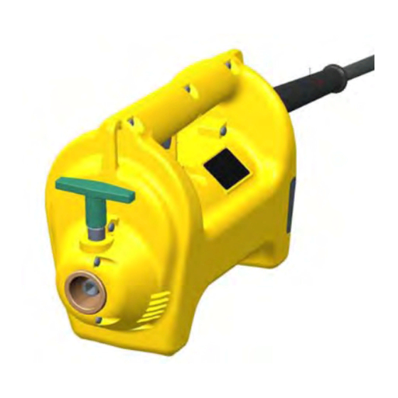
Drive motor M1500, M2500 for modular internal vibrator HMS Model M1500, M2500 Document 5100020149 Issue 06.2015 Version Language...
Page 2
Manufacturer Wacker Neuson Produktion GmbH & Co. KG Preußenstraße 41 80809 München www.wackerneuson.com Tel.: +49-(0)89-354 02-0 Fax: +49-(0)89-354 02-390 Translation of the original operator’s manual in German 100_0000_0001.fm...
Storage location of the manual ....................6 Accident Prevention Regulations....................6 Additional information ........................6 Target group ..........................6 Explanation of symbols........................ 6 Wacker Neuson Contact partner ....................7 Limitation of liability........................7 Product identification of the machine................... 7 Security ..........................8 Policy ............................8 Qualification of the operating personnel ..................
Page 4
Inhaltsverzeichnis Disposal ..........................36 14.1 Disposal of waste electrical and electronic equipment .............. 36 Accessories .........................37 Technical data ........................38 16.1 Drive motor ..........................38 16.2 Flexible shaft-E (optional) ......................38 16.3 Flexible shaft-S (optional) ......................39 16.4 Vibrator head standard (optional) ....................39 16.5 Vibrator head HA (optional) .......................
This operator's manual contains information and procedures for the safe operation and safe maintenance of your Wacker Neuson machine. For your own safety and to protect against injuries, you must thoroughly read the safety instructions, familiarize yourself with them and observe them at all times.
The information contained in this manual is based on machines that were manufactured at the time of printing. Wacker Neuson reserves the right to make unannounced modifications to this information. It must be ensured that possible modifications or supplements on the part of the manufacturer are introduced in this manual immediately.
NOTE Supplementary information. Wacker Neuson Contact partner Depending on your country, your Wacker Neuson contact partner is Wacker Neuson service, a Wacker Neuson affiliate or a Wacker Neuson dealer. On the Internet under www.wackerneuson.com. The manufacturer's address is found at the beginning of this manual.
In particular, the following cases are considered structural changes: Opening the device and permanent removal of components that originate from Wacker Neuson. Installing new components that do not originate from Wacker Neuson or are not comparable in the design system and quality of the original parts.
Page 9
You can find more information in the chapter Troubleshooting. Spare parts, accessories Only use spare parts from Wacker Neuson or such spare parts that are comparable in the design system and quality of the original parts. Only use accessories by Wacker Neuson.
This is why you may have to wear ear protection under certain circumstances. You can find the exact value in the chapter Technical data. Work particularly cautiously and pay attention when wearing ear protection, as your ability to hear noises, such as screams or signal tones, is restricted. Wacker Neuson recommends always wearing ear protection. 100_0101_si_0007.fm...
3 Security Transport Switch off the unit Before transport, switch the equipment off and remove the plug from the plug receptacle. Allow the engine to cool down. Transporting the equipment Secure the equipment on the means of transport from tipping over, falling down or sliding. Recommissioning Before recommissioning, attach and fasten equipment, equipment parts, accessories or tools that were dismantled for transport purposes.
3 Security Protect the flexible shaft (component of the HMS) Do not excessively bend or kink the flexible shaft. Do not pull the flexible shaft over sharp edges. If the flexible shaft has become jammed in the reinforcement, switch off the drive motor and disconnect the flexible shaft from the drive motor.
Page 13
(only equipment of class rating I, see chapter Technical data). You may only use tested extension cables that are suitable for construction site use: Wacker Neuson recommends H07RN-F, H07BQ-F, a SOOW-cable or a country-specific equivalent design.
Care and maintenance work may only be carried out insofar as it is described in this operator's manual. All other work, such as the replacement of the power cable, must be performed by the Wacker Neuson contact partner in order to avoid safety hazards.
4 General Power Tool Safety Warnings General Power Tool Safety Warnings WARNING Read all safety warning, instructions, illustrations and specifications provided with this power tool. Failure to follow all instructions listed below may result in electric shock, fire and/or serious injury. Save all warnings and instructions for future reference.
Page 16
4 General Power Tool Safety Warnings c) Protective equipment such as dust mask, non-skid safety shoes, hard hat or hearing protection used for appropriate conditions will reduce personal injuries. d) Prevent unintentional starting. Ensure the switch is in the off-position before connecting to power source and/or battery pack, picking up or carrying the tool.
Page 17
4 General Power Tool Safety Warnings k) Properly maintained cutting tools with sharp cutting edges are less likely to bind and are easier to control. Use the power tool, accessories and tool bits etc. in accordance with these instructions, taking into account the working conditions and the work to be performed. m) Use of the power tool for operations different from those intended could result in a hazardous situation.
5 Safety and information labels Safety and information labels There are labels on your unit that contain important instructions and safety information. Keep all labels legible. Replace missing or illegible labels. The item numbers on the labels can be found in the parts book. 1, 2, 3 Item Label...
6 Setup and function Setup and function Standard package The standard package includes: Drive motor. Shoulder strap. Operator’s manual. The HMS consists of several components, see chapter Technical Data: Drive motor. Flexible shaft (optional). Vibrator head (optional). ...
7 Components and operator's controls Components and operator's controls Components and operator's controls of the drive motor Item Designation Item Designation ON/OFF switch Air outlet Handle T-Handle Air inlet Lugs for shoulder strap T-Handle The t-handle has different colors for the different versions, see chapter Technical Data. With the t-handle, the quick disconnect coupling is opened so as to allow for a quick replacement and a secure connection link of the flexible shaft to the drive motor.
7 Components and operator's controls Components of the flexible shaft (optional) Item Designation Item Designation Connection to the drive motor Bend protection Coupling piece Connection to vibrator head Components of the vibrator head (optional) Item Designation Item Designation Fitting Shaft core adapter 100_0101_cp_0011.fm...
8 Transport, entire system (HMS) Transport, entire system (HMS) WARNING Improper handling can lead to injuries or serious damage to property. Read and observe all safety instructions in this operator's manual, see chapter Safety. WARNING Hot vibrator head. Contact may cause burns. Only touch the vibrator head once the engine has cooled down.
9 Assembly of the HMS Assembly of the HMS Pre-assemble the vibrator head WARNING Rotating parts. Hand injuries are possible. Switch off the drive motor. Disconnect the flexible shaft from the drive motor. Working in the workshop Perform maintenance jobs in a workshop on a workbench. This has the following advantages: Protection of the equipment from dirt on the construction site.
Page 24
9 Assembly of the HMS Connect the flexible shaft to the drive motor Item Designation Item Designation Flexible shaft T-Handle Coupling piece 1. Switch the drive motor off with the ON/OFF switch. 2. Pull the plug out of the plug receptacle. 3.
The flexible shaft (including vibrator head) is coupled with the drive motor. NOTICE For longer flexible shafts, Wacker Neuson recommends using a shoulder strap. Check equipment Check the HMS and all components for damage. Check for a firm seat of the flexible shaft in the drive motor.
Page 26
10 Operation WARNING Start-up of the equipment. Risk of injury from uncontrolled start-up of the equipment. Switch the equipment off before connecting to the electric power supply. Switch on the equipment Item Designation ON/OFF switch 1. Hold the equipment with one hand. 2.
10 Operation 10.3 Decommissioning Switch off the unit CAUTION Proper motion of the running vibrator head outside of the freshly mixed (green) concrete. Risk of injury or danger of property damage due to beating around vibrator head. Switch the equipment off before setting it down. ...
The maintenance work described in this operator's manual may be performed by any responsible operator, unless indicated otherwise. Some maintenance work may only be performed by special technically trained personnel or by the service department of your Wacker Neuson contact partner — these jobs are marked separately. 11.2 Maintenance schedule NOTICE The time intervals named here are standard values for normal operation.
bushing. Replace the oil in the vibrator head.* Have this work performed by the service department of your Wacker Neuson contact partner. 11.3 Maintenance work Working in the workshop Perform maintenance work in a workshop on a workbench. This has the following advantages: Protection of the equipment from dirt on the construction site.
Page 30
11 Maintenance 11.3.2 Drive motor Clean the filter element Item Designation Item Designation Screw Filter element Cover 1. Switch the ON/OFF switch off. 2. Wait until the equipment has come to a complete standstill. 3. Pull the plug out of the plug receptacle. 4.
Page 31
11 Maintenance 4. Remove the shaft core entirely from the protection hose. 5. Wipe down the shaft core with a clean, lint-free cloth. NOTICE Do not clean the shaft core or the protection hose with a solvent! 6. Clean the thread of the coupling and the flexible shaft with a wire brush and cleaning agent. Exchange the plastic bushing Item Designation...
Page 32
Minimum wrench size of the square (HA-vibrator head). The wear is highest at the end of the vibrator head. If a wear dimension is reached at one point, have the tube bottom exchanged by your Wacker Neuson contact partner. Vibrator head...
Page 33
11 Maintenance Replace the oil in the vibrator head Item Designation Item Designation Housing Shaft core adapter Fitting Open the vibrator head 1. Remove dirt accumulation within the range of the fitting. 2. Clamp the flexible shaft in a vise with prism jaws. 3.
Lubricate the shaft core. insufficiently lubricated. Bearing of the vibrator head or the Have the equipment parts exchanged.* drive system worn. Rotor grinding on the stator. Have this work performed by the service department of your Wacker Neuson contact partner. 100_0101_ts_0009.fm...
Excess wear and damage to the components is possible. Only use permissible combinations of components. Vibrator head Flexible shafts SM1-E SM2-E SM4-E H25 S M1500 or M2500 H25 HA Vibrator head Flexible shafts SM0-S SM1-S SM2-S SM3-S SM4-S SM5-S...
14 Disposal 14 Disposal 14.1 Disposal of waste electrical and electronic equipment For customers in EU countries This device is subject to the European Directive on waste electrical and electronic equipment (WEEE) and the corresponding national legislation. The WEEE directive outlines the procedure for handling electrical waste equipment across the EU.
You need the pipe thread seal to seal the threaded connections between the vibrator head and flexible shaft as well as between the coupling and the flexible shaft. Special lubricant for the flexible shaft You need the Wacker Neuson special lubricant to lubricate flexible shaft cores in flexible shafts. 100_0101_ac_0005.fm...
16 Technical data 16 Technical data 16.1 Drive motor Designation Unit M1500/120 US M2500/120 US Item no. 5100004500 5100006000 T-handle (color) green Rated current 12.5 15.0 Rated voltage Rated frequency 50 – 60 50 – 60 Phases Length mm (in) 312 (12.3)
You can find the model designation and voltage of your equipment on the nameplate or using the item number from the chapter Technical data. Machine Voltage Extension Cross-section area of cable M1500 US 120 1~ < 25 < 42 < 66 < 98 <...
Page 41
16 Technical data Example: You have a M1500/120 and would like to use a 40-meter long extension cable. The equipment has 120 V input voltage. According to the table, your extension cable must have a stranded conductor cross-section of 2.5 mm...
17 Glossary 17 Glossary Class rating The class rating according to DIN EN 61140 specifies the safety measures for electrical equipment to avoid electrocution. There are four class ratings: Class rating Meaning No special protection apart from the basic insulation. No grounded conductor.